Category Archives: tank experiment

Nansen’s dead water explained on YouTube

Remember the experiment on Nansen’s observation of “dead water” that Elin & myself set up as part of GEOF213? Our movies of this experiment are now featured in a brilliant Youtube video by my friend, the german science communicator Doktor Wissenschaft! Check it out! (English subtitles available)

I feel so proud to have contributed to such a cool video! :-)


P.S.: Doktor Wissenschaft also has an Instagram profile which is totally worth checking out. He posts interesting physics, chemistry and biology facts in twice daily. And occasionally he includes cool ocean and climate facts, supplied by yours truly. If you have fascinating facts that should be featured on Doktor Wissenschaft, please feel free to let me know and I will happily forward them!

One of Doktor Wissenschaft’s facts on Instagram: “If all Antarctic ice did melt, sea level would rise by approximately 58 meters”

Thermal forcing in a non-rotating vs rotating case: Totally different results

On Thursday, I wrote about the thermally driven overturning circulation experiment that Torge and I did as past of our “dry theory 2 juicy reality” experiments, and mentioned that it was a non-rotating experiment in a class about rotating fluid dynamics.

I showed you the rectangular tank, but we also used a cylindrical tank with cooling in the middle that is a rotational symmetric version of the “slice” in the rectangular tank. In both cases we see the same: Cold water sinks and spreads at the bottom and is then replaced by warmer water.

But when we start turning the cylindrical tank with the cooling in the middle, cool things start to happen. I’ve blogged about that experiment before, but here is a pic of the circulation that develops. Instead of an overturning, we now get heat transport via eddies!

This is actually a really nice way to show again how hugely important the influence of rotation is on the behaviour of the ocean and atmosphere!

Salt fingers in my overturning experiment

You might have noticed them in yesterday’s thermally driven overturning video: salt fingers!

In the image below you see them developing in the far left: Little red dye plumes moving down into the clear water. But wait, where is the salt? In this case, the “double” in double diffusion comes from heat and dye which are diffusing at different rates. As temperature’s molecular diffusion is about 100x faster than that of salt (or other things that have to physically change their distribution, rather than just bump into each other to transfer energy), the red and clear water quickly have the same temperature, but then the red dye makes the red water more dense, hence it sinks.

Over time, those fingers become more and more clearly visible…

Until after a couple of minutes, we see that they are really contributing to mixing between the two layers.

Even though double diffusive mixing happens in the ocean, too, the scaling of these fingers is of course totally off if we think of this tank as for example the northern half of the Atlantic. But then so is the density stratification… But it’s always good to keep in mind that while this experiment is showing some things quite nicely, there are also things that are artefacts of the way the experiment is set up and that aren’t analogous to how things work in the ocean.

A really nice and very new-to-me way of observing them is from above:

This is a picture that was taken fairly early in the experiment, when the layers hadn’t propagated far yet and the salt fingers weren’t being pulled back by the shear between the layers. But it’s nice to see how the dye is concentrated in those downward moving fingers, isn’t it?

Thermally driven overturning circulation

Today was the second day of tank experiments in Torge’s and my “dry theory 2 juicy reality” teaching innovation project. While that project is mainly about bringing rotating tanks into the theoretical teaching of ocean and atmosphere dynamics, today we started with the non-rotating case of a thermally driven overturning circulation.

Very easy setup: A rectangular glass vase filled with luke-warm water. A frozen cool pack for sports injuries draped over one end (which we’ll think of as the northern end) provides the cooling that we need for deep water formation. The deep water is conveniently dyed blue with food dye. Red food dye is warmed up and added to the “southern end” of the tank, and voilà! An overturning circulation is set up.

Watch the sped-up movie to see what happens:

As you will notice, this circulation won’t last for a very long time. Since we are adding neither warming nor mixing, the cold water will eventually fill up the tank. But it’s still quite a nice experiment!

(And should you have noticed the “salt fingers” forming towards the end of the movie, I’ll write about those tomorrow)

And here is the nice group of students that humoured me and posed for this picture. It’s fun with such a motivated group that comes up with new things to try all the time! :-)

If one rotating table is awesome, four rotating tables are…?

I’m actually at a loss for words. Amazing? Spectacular? So much fun? All of that!

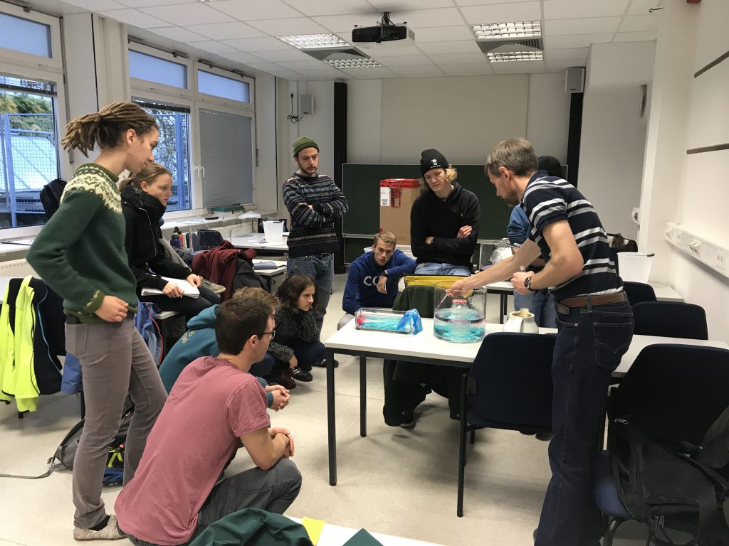
Today was the first time Torge and I tried our four DIYnamics-inspired rotating tables in teaching. (Remember? We want to use 4 rotating tables simultaneously so students can work in small groups rather than watching us present experiments, and also so we could quickly see how slightly different conditions might lead to different results. Having 4 tanks running at the same time cuts down on a lot of spin-up wait time! And we wanted affordable rotating tables so a) we could afford them and b) students would really just be able to play without them, or us, being afraid that they might break something). And it went even better than we had hoped, and we were already pretty convinced that it would be awesome!

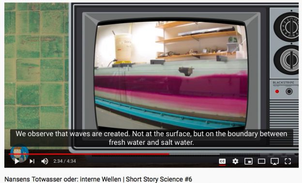
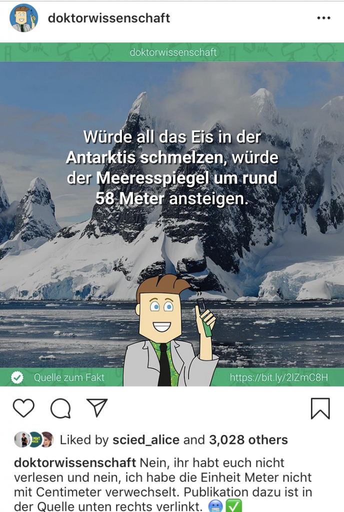
It all started out, even before class started, with one of the students asking if it was me who had done the recent takeover of Kiel University’s Instagram account with the awesome tank experiments in Bergen. Yep, that was me, and it was great that she remembered she had seen the experiments and even recognized me! Made me very happy. If I had needed convincing that social media is awesome, here it was!

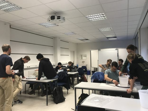
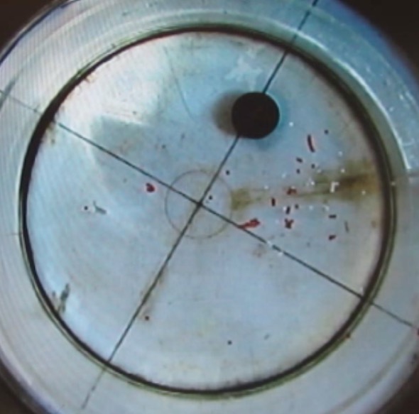
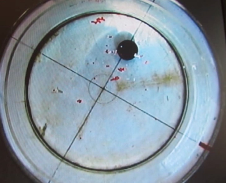
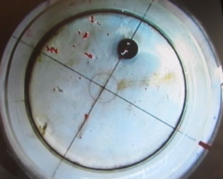
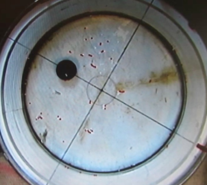
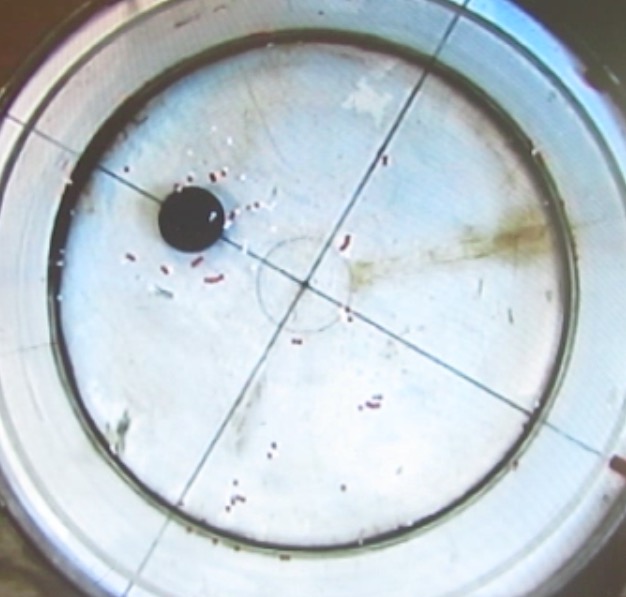
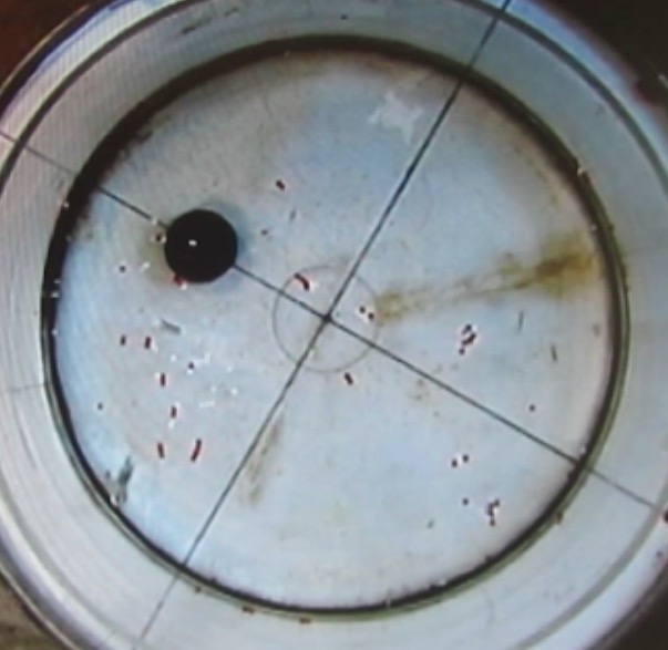
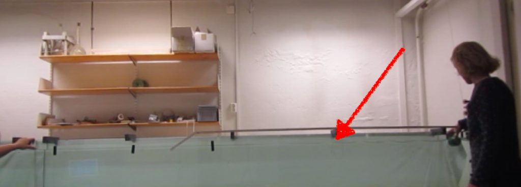
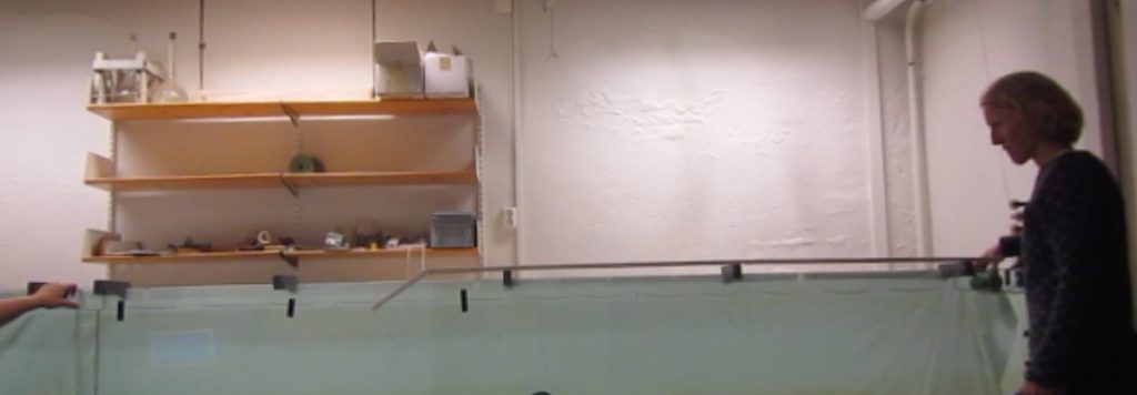
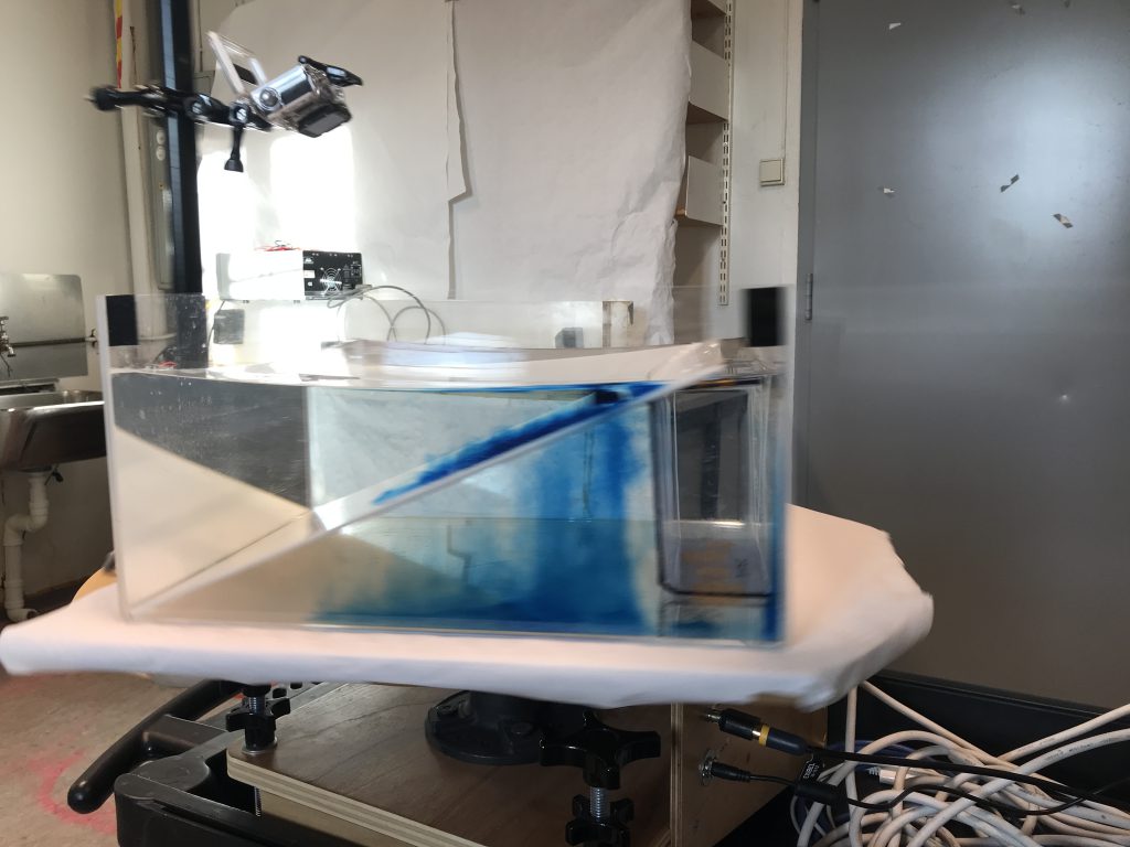
But then the students started playing, and they got really into it. We started out with just tanks filled with water on the Lazy Susans, and the students moved them by hand to get a feel for how water behaves under rotation. We looked at deformation of surfaces, how confetti as tracers behaved on the surface and on the bottom, all the good stuff. Already with such simple experiments there is so much physics to discuss!

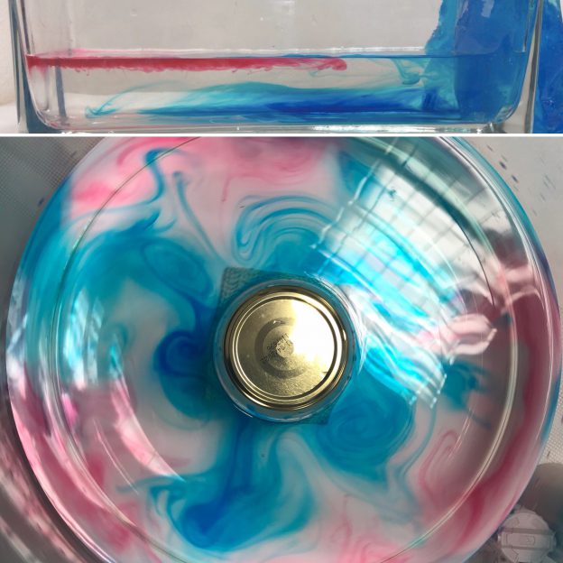
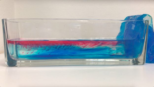
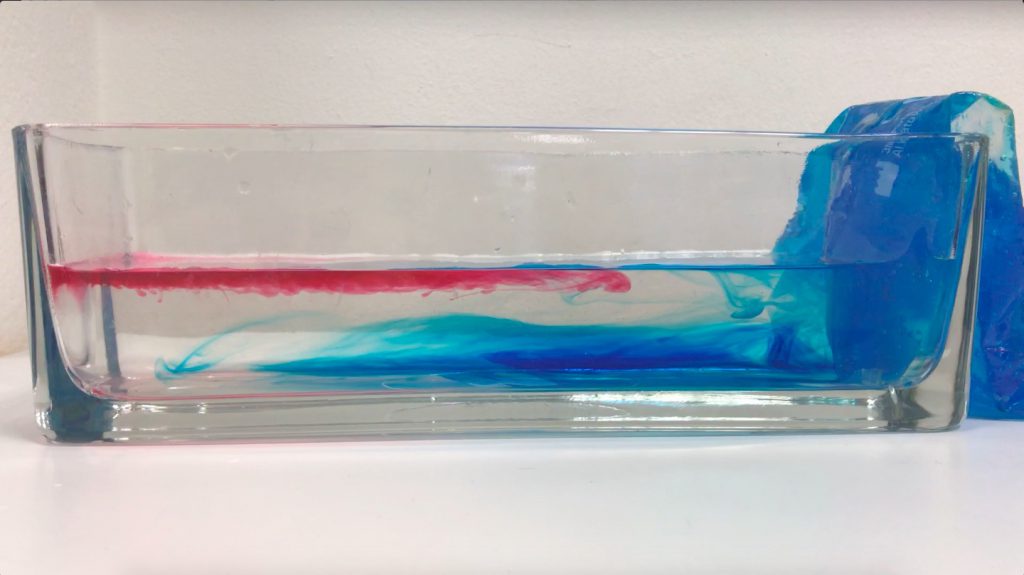
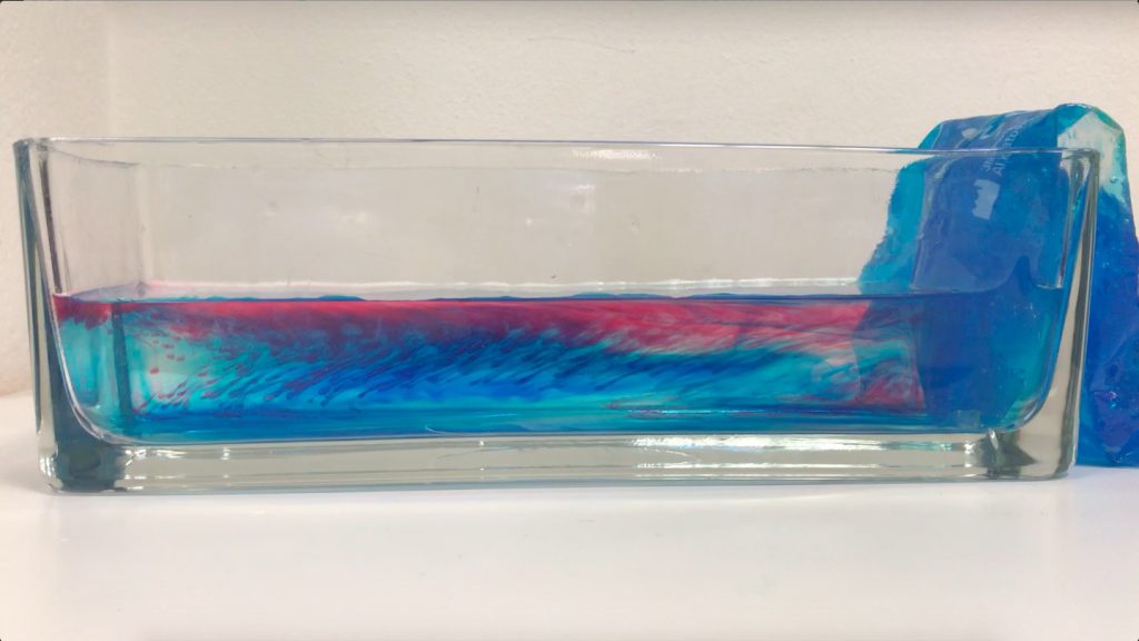
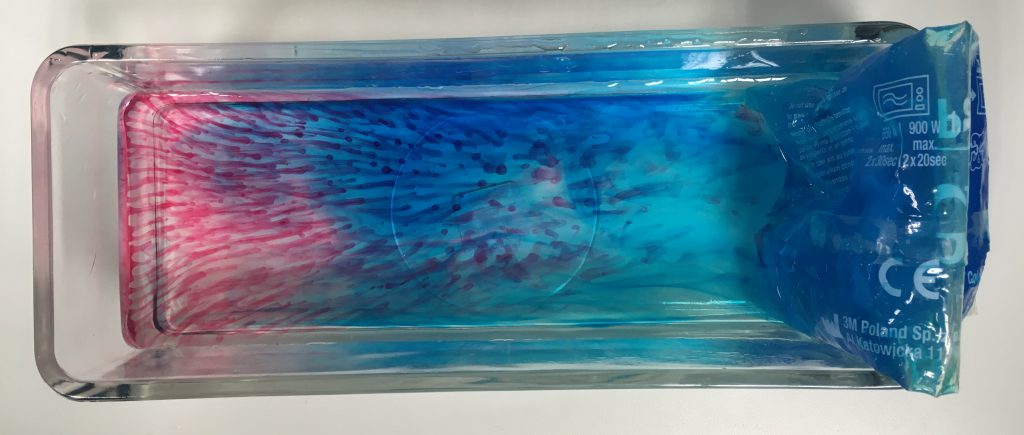
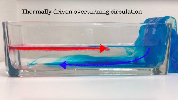
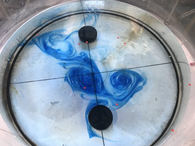
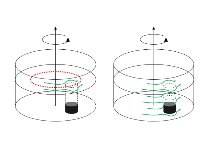
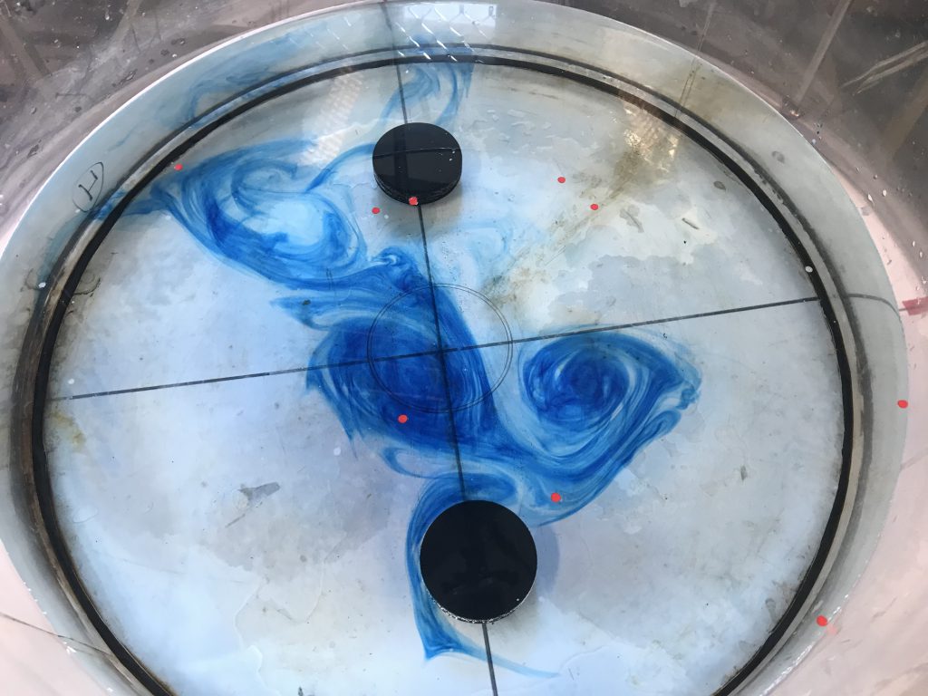
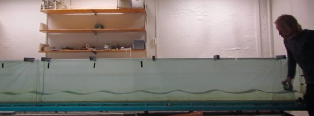
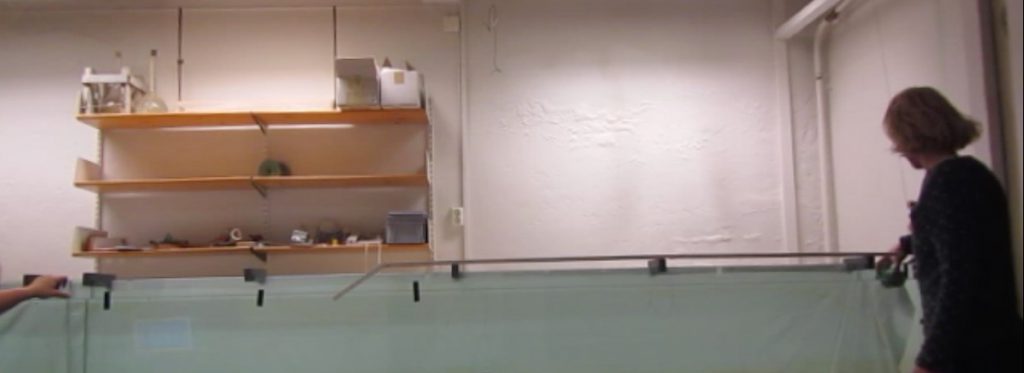
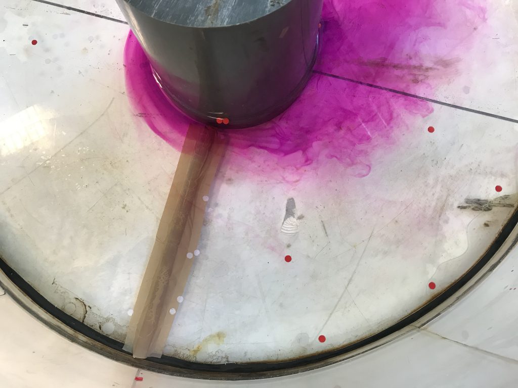
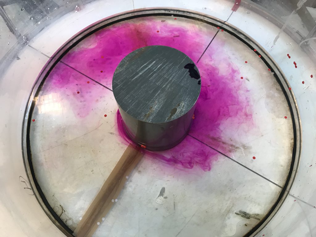
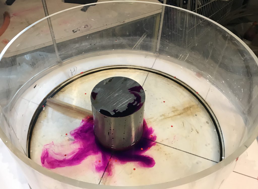
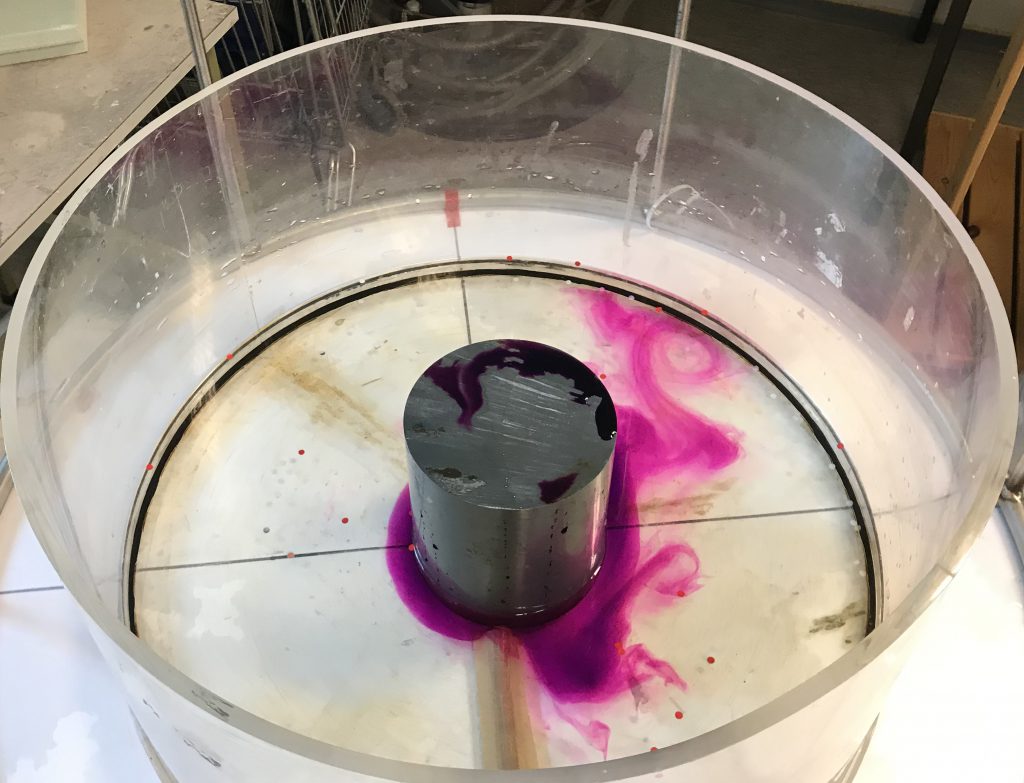
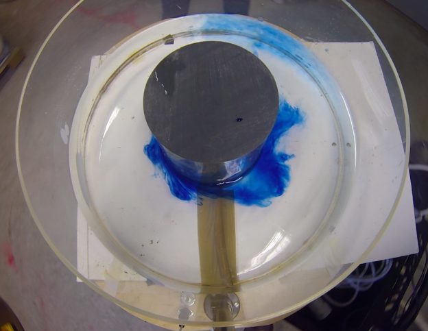
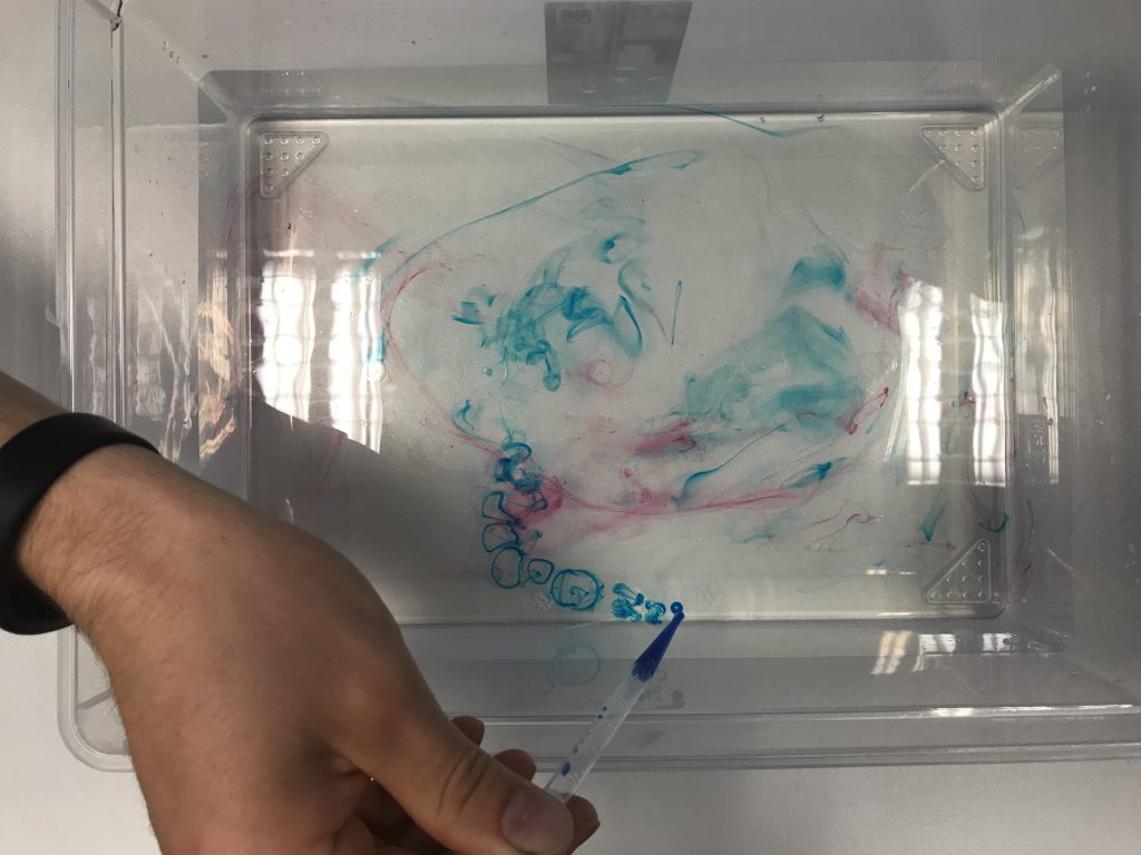
And then we moved on to turbulence in a non-rotating and rotating system. Look at the cool vortex rings you can make with food coloring :-)

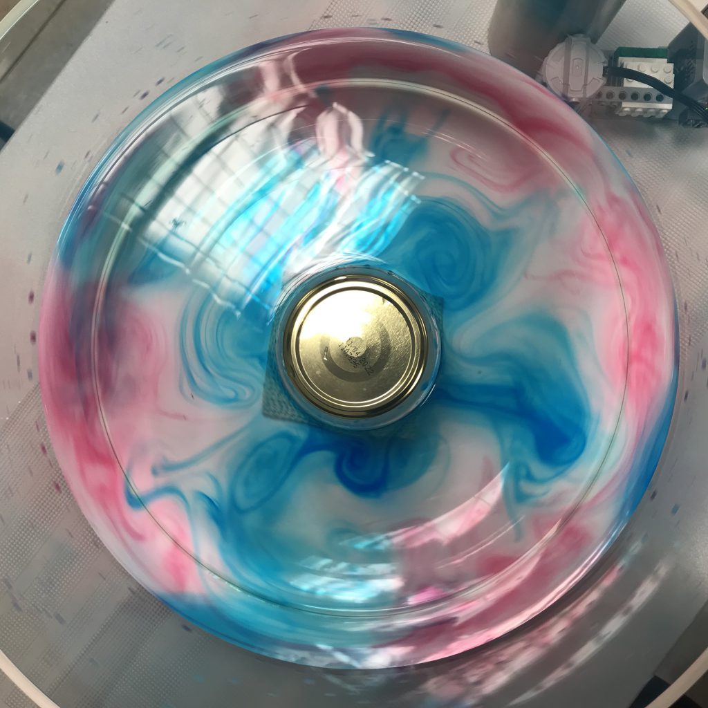
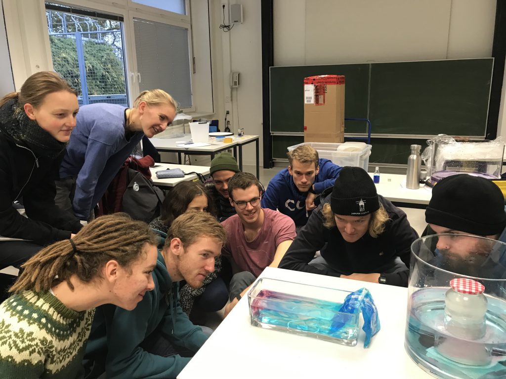
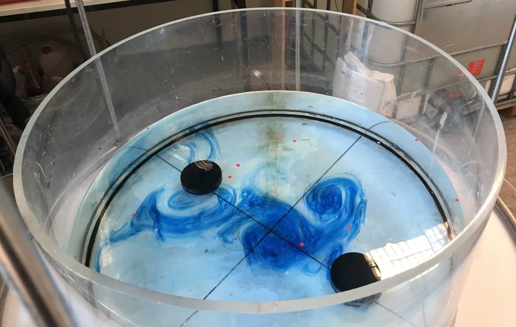
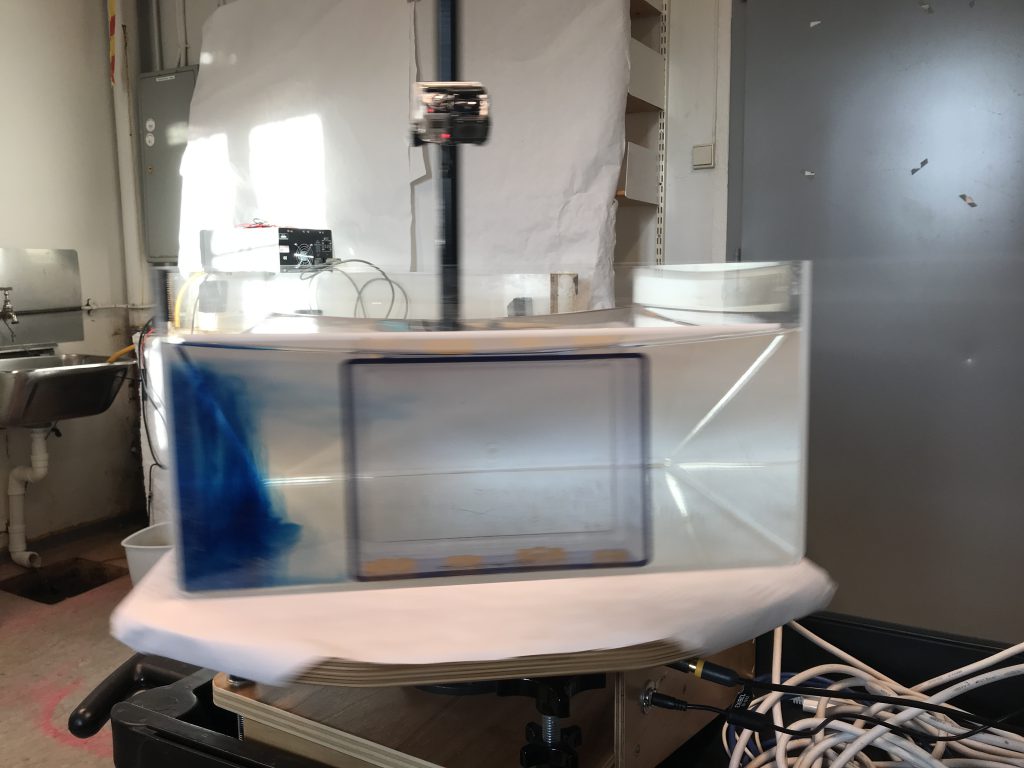
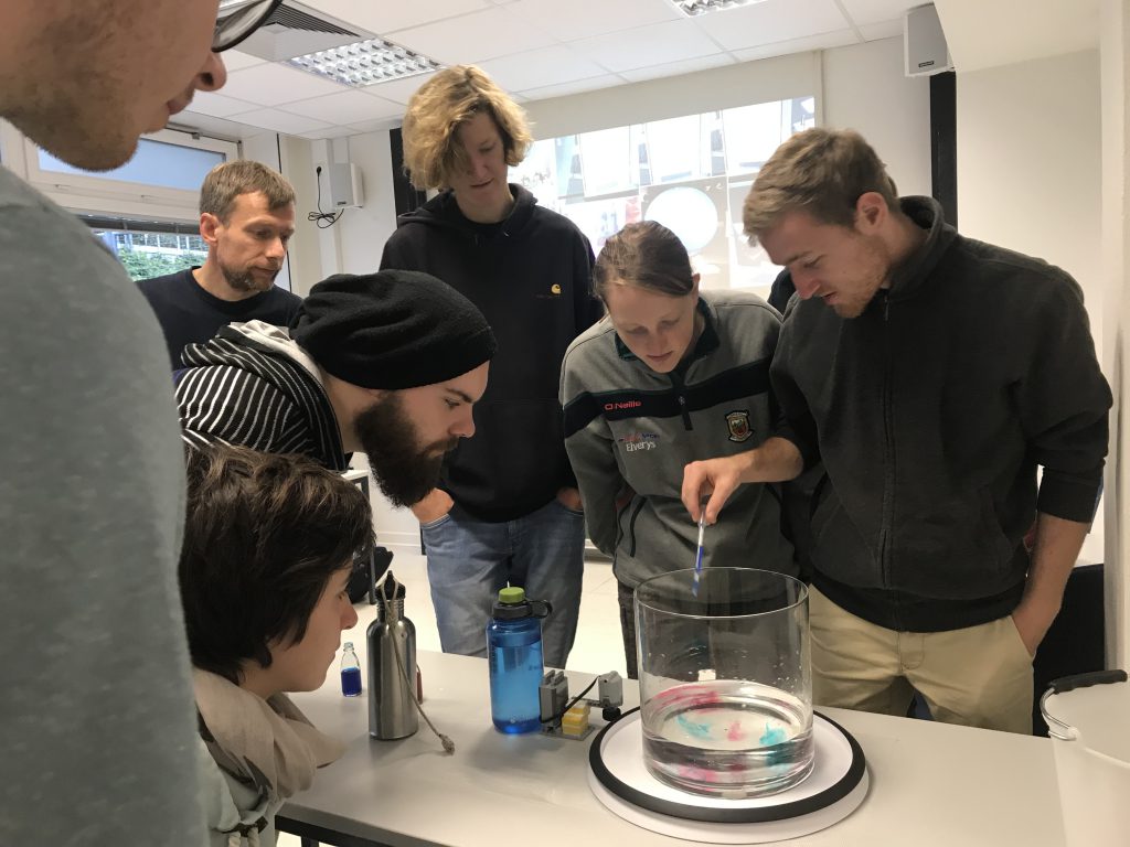
And then we moved on to turbulence in the rotating system. Our final tanks haven’t arrived yet, so we made do with whatever we had at hand (see the green bowl as tank below…). Students also started improvising to include a topography and other modifications that we hadn’t planned for. This is so great if students are so keen to figure things out that they take the initiative to make it happen themselves!

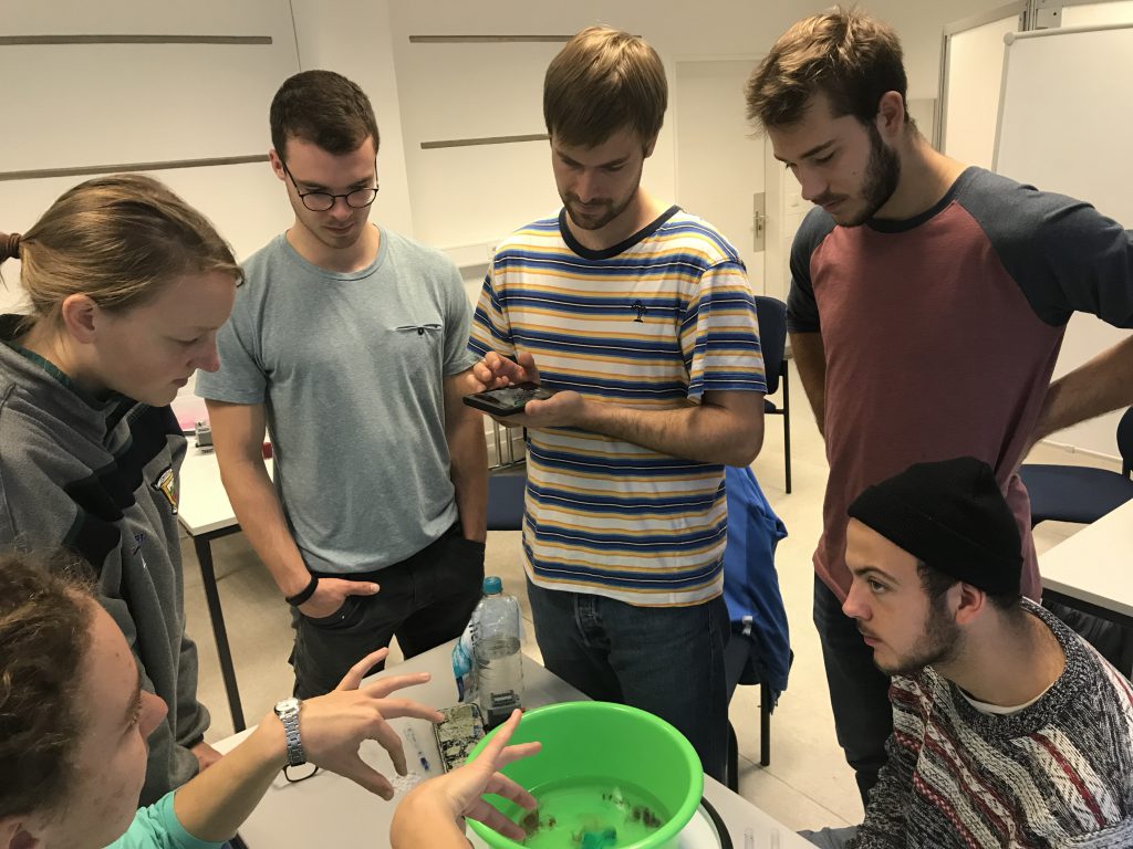
Judging from what I could observe, students were really enjoying themselves and got into deep discussions, trying to connect their observations to the theory they had learned. Additionally, there were lots of “oh wow!”s and “coooool”s everywhere. And I overheard this one exchange between two students: “careful, don’t drop the phone into the tank!” “oh, it’s ok, it’s waterproof” “I don’t care about the phone, I don’t want you to mess up the experiment!” :-D

Btw, note below the small Lego motor that drives the Lazy Susan. That’s really the whole setup. Speaking of affordable and easy. And portable. And all-around awesome!

And it was great fun for Torge and me, too, to observe what the students were up to, and to discuss with them. There were already several curious questions as to what experiments we are planning to do throughout the course. The next sessions, Torge will connect the experiments we did today to theory, and start on the theory we need for the next set of experiments we are planning to run, but I can’t wait to continue working with the tank experiments with such a motivated group of students! :-)

Taylor column

I was super keen on trying the Taylor column experiment, but maybe I expected things to look too much like my sketch below, or my technique isn’t quite perfect yet, but in any case, the results don’t look as good as I had hoped.

This is the setup I was aiming for:

  • put ice hockey puck (two in our case), ca 1/5th water depth, ca 1/4 diameter of tank
  • rotating our tank at 5rpm (ca 7 on GFI’s large tank’s display) with the obstacle in the water until solid body rotation is reached (We know that solid body rotation is reached if paper bits distributed on surface all rotate at same rate as the tank).
  • change the rotation rate a tiny little bit so water moves relative to tank and obstacle, i.e. we have created a current flowing in the rotating system.

And here is what happened.

First attempt.

  • tank was rotating way too fast
  • tank wasn’t in solid body rotation because it wasn’t level
  • one of the hockey pucks didn’t stay in place but moved to the edge of the tank as the tank (slowly!) accelerated
  • more confetti on the surface!

But! We see that there is clearly something happening around the hockey puck that seems to deform the curtain of blue dye.


Second attempt.

  • Stopped too rapidly / bumpy

Even though the blue dye curtain moves over the pucks initially, we see that they develop a wake or something, deforming the dye.


Third attempt.

Accidentally deleted the movie, so we will have to make do with a couple of pics I took while the experiment was running.

Slowing down worked a lot better this time round. We clearly see that the dye curtains are deformed around the Taylor columns and don’t move over the pucks.


Fourth attempt.

I think I am finally accepting that this way of introducing dye as a tracer isn’t working as I had hoped…

And this is when my camera decided to stop working…

Fifth attempt.

Back to the basics: Confetti floating on the surface.

Before slowing down, the field of confetti looked like this.

Then, the tank was slowed down and the field got deformed. Some confetti went over the puck, but there is an eddy downstream of it that catches confetti.

And the confetti that went over the puck seem to be stuck there.


Final attempt (for now).

More confetti. This is the situation before slowing down the tank:

Confetti distribution is influenced by the puck similarly to what we saw in the dye: Some confetti are slowed down upstream, some move around the puck.

Eventually, most confetti end up in the puck’s wake.

Phase and group velocities in deep and shallow water

When Tor came to visit me in GFI’s basement lab a couple of days ago, he told me about an experiment he had seen in Gothenburg in the seventies. So Elin and I obviously had to recreate it on the spot. Therefore today, we are comparing phase- and group velocities in deep and shallow water!

Waves are excited by means of an oscillating, hand-helt beer can, curtesy of the beer brewing club at GFI. The experiments are filmed and wave lengths and phase velocities are determined from the videos, which is a lot easier than measuring them directly while the experiment is being run.

Shallow water waves

For shallow water, we are using a water depth of 10 cm. Waves are very easy to see and phase velocities are equally easy to measure.

There is another experiment on (standing) shallow water waves being run at GFI the year before students attend GEOF213, which I described back in 2013.

Deep water waves

For deep water waves, we use a water depth of 42.5 cm (the exact number only matters when the tank filling is also used to fiddle with the dead water experiment, as I had been when the idea for this experiment came up).

Typical wave lengths that are easy to do are between 10 and 25 cm (wave lengths obviously have to be short enough that the water is still “deep”, i.e. H>>wave length) — Elin’s instruction to me for the kind of waves she wanted was “Allegro!” :-D Elin, you are really the coolest and most fun person to play with tanks with!

In deep water, we now have the added difficulty that the phase speed is twice as fast as the group speed. This makes observing the whole thing a lot more difficult. Also amplitudes are a lot smaller now, since the tank was so full and we wanted to keep the water inside…

Here is t0 — Elin has just dipped the beer can into the water for the first time

t1 — can you see the wave signal has propagated up to where the red arrow is pointing to?

t2 — the signal has reached my thumb at the left edge of the picture.

From timing this, we can calculate the group speed. We can also measure the wave length on the video and then calculate a theoretical phase speed from that. For the experiments Elin and I did, the results were pretty good, as in phase speed was usually about twice as fast as group speed. And I am curious to hear how well this works out when the students run the experiment!

Topographic Rossby waves in a tank

This experiment just doesn’t want to be filmed by me. Even though I spent more time on preparation of this experiment than on almost any other experiment I have ever done! I have written up the theory behind this experiment, run it with a blob of dye to visualize the wave, then with a ring of dye. But for some reason, something goes wrong every time. Like people opening the door to the lab to come and visit me just the very second I am about to put dye into the tank, resulting in me jumping and a lot of dye ending up in the wrong spots… Or the tank itself getting the hickups. Or the cameras not playing nicely if for once the experiment itself goes well.

Anyway, it is still a very cool experiment! So here are some pictures.

In all those pictures, the tank is rotating a lot more slowly than recommended in the instructions. I thought that might make it all easier to run (5rpm; dial at approximately 7 for GFI big tank, similar to Taylor column). And it looks just fine, except that the restoring force back to the middle isn’t really there (as was to be expected, since the surface is almost flat and the parabolic shape is needed for a difference in water depth).

Third attempt

Below, you see the “ridge”, a piece of hose that connects a solid cylinder in the middle of the tank to the tank’s outer wall. The tank is turning counter-clockwise.

The flow looks substantially different upstream and downstream of the ridge: Upstream, it is laminar and close to the middle cylinder. Downstream, it’s meandering (the Rossby waves!) and diffusive.

Fifth attempt (same as above)

In this experiment, the difference between the flow up- and downstream of the ridge are even more obvious. Look at those eddies!

It’s quite amazing to see how a small disturbance can make the entire system unstable.


Planetary Rossby waves — a side view

What I find really fascinating about the planetary Rossby wave experiment is to look from the side and see the columns develop and move around the tank.

Here is a side-view camera plus the top view, both cameras rotating with the tank. The movie is sped up 20x so in about 22 seconds, you will have a good idea of what happens:

And here is the same movie in real time. Here you can really beautifully watch the plumes of dense water sinking to the bottom while the whole column is rotating.

One thing to avoid when running this experiment: Don’t put the ice cube too close to the side of the tank, otherwise it will get stuck there. I don’t know if it was surface tension keeping it so close to the wall or if, since it couldn’t rotate, it decided not to move at all, but in any case: If the ice cube is too close to the wall, it will get stuck. In our case, the dense water then sank down in the small gap between the sloped bottom and the wall of the tank (as you see in the picture below, which is looking under the sloping bottom towards the deep end of the tank).

You still see columns forming underneath the sloping bottom, but that wasn’t quite what we were aiming to do…


Topographic Rossby wave

Next attempt at the topographic Rossby wave! This time with following the geosci.uchicago.edu instructions more closely…

…and then the tank had hickups, so we did get waves, but a lot more diffusive than we had hoped, because the tank slowed down a lot more and in a more bumpy fashion than I had planned…

Setup of the topographic Rossby wave experiment

For a demonstration of topographic Rossby waves, we want the Coriolis parameter f to stay constant but have the depth H change. We use the instructions by geosci.uchicago.edu as inspiration for our experiment and

  • build a shallow ridge into the tank, from a cylinder in the middle to the outer wall. My solution: Take a 1.5 cm (outer) diameter hose, tape it to the bottom of a tank to achieve a ridge with smooth edges
  • 7 cm water depth
  • spin up the tank to approximately 26 rpm
  • wait for it to reach solid body rotation (ca 10 min)
  • introduce dye all around the cylinder in the middle
  • reduce rotation slightly, to approximately 23 rpm so the water inside the tank moves relative to the tank itself, and thus has to cross the ridge which is fixed to the tank
  • watch it change from laminar flow to eddies downstream of the ridge. Hopefully ;-)