Tag Archives: Topographic Rossby wave

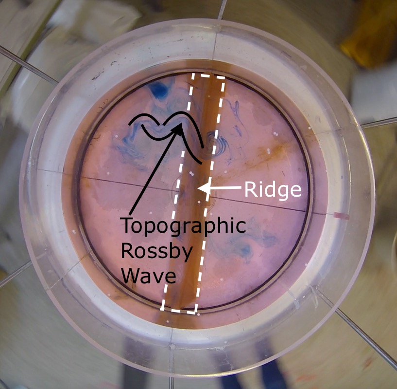
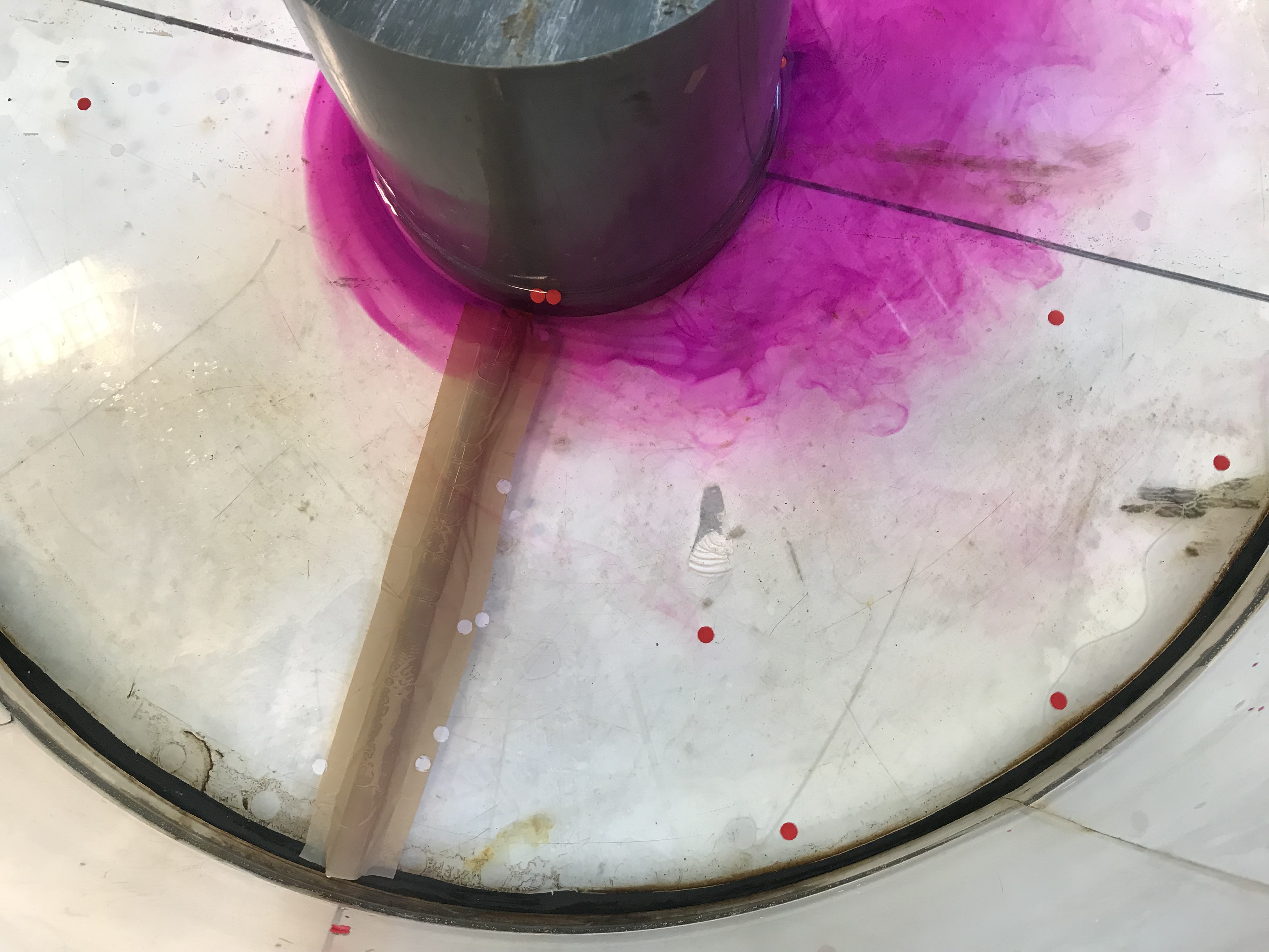
Topographic Rossby waves in a tank

This experiment just doesn’t want to be filmed by me. Even though I spent more time on preparation of this experiment than on almost any other experiment I have ever done! I have written up the theory behind this experiment, run it with a blob of dye to visualize the wave, then with a ring of dye. But for some reason, something goes wrong every time. Like people opening the door to the lab to come and visit me just the very second I am about to put dye into the tank, resulting in me jumping and a lot of dye ending up in the wrong spots… Or the tank itself getting the hickups. Or the cameras not playing nicely if for once the experiment itself goes well.

Anyway, it is still a very cool experiment! So here are some pictures.

In all those pictures, the tank is rotating a lot more slowly than recommended in the instructions. I thought that might make it all easier to run (5rpm; dial at approximately 7 for GFI big tank, similar to Taylor column). And it looks just fine, except that the restoring force back to the middle isn’t really there (as was to be expected, since the surface is almost flat and the parabolic shape is needed for a difference in water depth).

Third attempt

Below, you see the “ridge”, a piece of hose that connects a solid cylinder in the middle of the tank to the tank’s outer wall. The tank is turning counter-clockwise.

The flow looks substantially different upstream and downstream of the ridge: Upstream, it is laminar and close to the middle cylinder. Downstream, it’s meandering (the Rossby waves!) and diffusive.

Fifth attempt (same as above)

In this experiment, the difference between the flow up- and downstream of the ridge are even more obvious. Look at those eddies!

It’s quite amazing to see how a small disturbance can make the entire system unstable.


Topographic Rossby wave

Next attempt at the topographic Rossby wave! This time with following the geosci.uchicago.edu instructions more closely…

…and then the tank had hickups, so we did get waves, but a lot more diffusive than we had hoped, because the tank slowed down a lot more and in a more bumpy fashion than I had planned…

Setup of the topographic Rossby wave experiment

For a demonstration of topographic Rossby waves, we want the Coriolis parameter f to stay constant but have the depth H change. We use the instructions by geosci.uchicago.edu as inspiration for our experiment and

  • build a shallow ridge into the tank, from a cylinder in the middle to the outer wall. My solution: Take a 1.5 cm (outer) diameter hose, tape it to the bottom of a tank to achieve a ridge with smooth edges
  • 7 cm water depth
  • spin up the tank to approximately 26 rpm
  • wait for it to reach solid body rotation (ca 10 min)
  • introduce dye all around the cylinder in the middle
  • reduce rotation slightly, to approximately 23 rpm so the water inside the tank moves relative to the tank itself, and thus has to cross the ridge which is fixed to the tank
  • watch it change from laminar flow to eddies downstream of the ridge. Hopefully ;-)

Topographic Rossby wave

Finally trying the topographic Rossby wave experiment I wrote about theoretically here!

And it is working — ok-ish. If you know what you are looking for, you can kind of see it. So check out the picture above so you know what you expect to see below ;-) We are rotating the tank fairly rapidly (and there are a lot of inertial oscillations in the water even after a long spinup, don’t know why) and then slow it down just a little bit to create a current relative to the topography.

So it turns out that following instructions better might actually have been a good idea. We will do that some other day on a different rotating table.

Here is what we did today:

Setup of the topographic Rossby wave experiment

For a demonstration of topographic Rossby waves, we want the Coriolis parameter f to stay constant but have the depth H change. We use the instructions by geosci.uchicago.edu as inspiration for our experiment and

  • build a shallow ridge into the tank. My solution: Take a 2.3 cm (outer) diameter hose, tape it to the bottom of a tank to achieve a ridge with smooth edges
  • important difference to the geosci.uchicago.edu setup: We are just using our cylindrical tank without a solid cylinder in the middle. Therefore our ridge goes all the way across the tank. Main reason is that our rotating tank’s camera sits on six rods, so at fast rotations it is very difficult to insert dye and I thought this way might be easier. But that might not actually be true…
  • 10 cm water depth
  • spin up the tank to approximately 26 rpm (23 seconds for 10 rotations == 36.5 on the display of GFI’s large rotating table)
  • wait for it to reach solid body rotation (ca 10 min)
  • introduce dye upstream of the ridge,
  • reduce rotation slightly, to approximately 23 rpm (26 seconds for 10 rotations == 33 on the display of GFI’s large rotating table) so the water inside the tank moves relative to the tank itself, and thus has to cross the ridge which is fixed to the tank
  • watch it change from laminar flow to eddies downstream of the ridge. Hopefully ;-)