Rossby waves in a rotating tank — three different demonstrations
For both of my tank experiment projects, in Bergen and in Kiel, we want to develop a Rossby wave demonstration. So here are my notes on three setups we are considering, but before actually having tried any of the experiments.
Background on Rossby waves
I recently showed that rotating fluids behave fundamentally differently from non-rotating ones, in that they mainly occur in the horizontal and thus are “only” 2 dimensional. This works really well as long as several conditions are met, namely the water depth can’t change, nor can the rotation of the fluid. But this is not always the case, so when either the water depth or the rotation does change, the flow still tries to conserve potential vorticity and stay 2 dimensional, but now displays so-called Rossby waves.
Here are different setups for Rossby wave demonstrations I am currently considering.
Topographic Rossby wave
For a demonstration of topographic Rossby waves, we want the Coriolis parameter f to stay constant but have the depth H change. We use the instructions by geosci.uchicago.edu as inspiration for our experiment and
- build a shallow ridge into the tank. They use an annulus and introduce the ridge at a random longitude, we could also build one across the center of the tank all the way to both sides to avoid weird things happening in the middle (or introduce a cylinder in the middle to mimic their annulus)
- spin up the tank to approximately 26 rpm (that seems very fast! But that’s probably needed in order to create a parabolic surface with large height differences)
- wait for it to reach solid body rotation (ca 10 min)
- reduce rotation slightly, to approximately 23 rpm so the water inside the tank moves relative to the tank itself, and thus has to cross the ridge which is fixed to the tank
- introduce dye upstream of the ridge, watch it change from laminar flow to eddies downstream of the ridge (they introduced dye at the inner wall of their annulus when the water was in solid body rotation, before slowing down the tank).
What are we expecting to see?

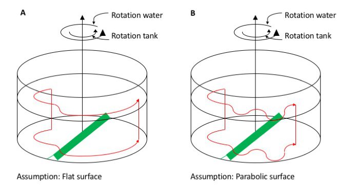
In case A, we assume that the rotation of the tank is slow enough that the surface is more or less flat. This will certainly not be the case if we rotate at 26rpm, but let’s discuss this case first, anyway. If we inject dye upstream of the obstacle, the dye will show that the current is being deflected as it crosses the ridge, to one direction as the water columns are getting shorter as they move up the ridge, then to the other direction when the columns are stretched going down the obstacle again. Afterwards, since the water depth stays constant, they would just resume a circular path.
In case B, however, we assume a parabolic surface of the tank, which we will have for any kind of fast-ish rotation. Initially, the current will move similarly to case A. But once it leaves the ridge, if it has any momentum in radial direction at all, it will overshoot its circular path, moving into water with a different depth. This will then again expand or compress the columns, inducing relative vorticity, leading to a meandering current and eddies downstream of the obstacle (probably a lot more chaotic than drawn in my sketch).
So in both cases we initially force the Rossby wave by topography at the bottom of the tank, but then in case B we sustain it by the changes in water depth due to the sloping surface.
My assessment before actually having run the experiment: The ridge seems fairly easy to construct and the experiment easy enough to run. However what I am worried about is the change in rotation rate and the turbulence and Ekman layers that it will introduce. After all, slowing down the tank is what we do create both turbulence and Ekman layers in demonstrations, and then we don’t even have an obstacle stuck in the tank. The instructions suggest a very slight reduction in rotation, so we’ll see how that goes…
Planetary Rossby waves on beta-plane
If we want to have more dramatic changes in water depth H than relying on the parabolic shape of the surface, another option is to use a rectangular tank and insert a sloping bottom as suggested by the Weather in a Tank group here. We are now operating on a Beta plane with the Coriolis parameter f being the sum of the tank’s rotation and the slope of the bottom.
Following the Weather in a Tank instructions, we plan to
- fill a tank with a sloping bottom (slope approximately 0.5)
- spin it at approximately 15 rpm until it reaches solid body rotation (15-20 minutes later)
- place a dyed ice cube (diameter approximately 5 cm) in the north-eastern corner of the tank
What do we expect to see?

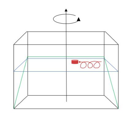
Ice cube and its trajectory (in red) on a sloping bottom in a rotating tank. Note: This sketch does not include the melt water water column!
Above is a simplified sketch of what will (hopefully!) happen. As the ice cube starts melting, melt water is going to sink down towards the sloping bottom, stretching the water column. This induces positive relative vorticity, making the water column spin cyclonically. As the meltwater reaches the sloping bottom, it will flow downhill, further stretching the water column. This induces more positive relative vorticity still, so the water column, and with it the ice cube, will start moving back up the slope until they reach the “latitude” at which the ice cube initially started. Having moved up the slope into shallower water, the additional positive vorticity induced by the stretching as the water was flowing down the slope has now been lost again, so rather than spinning cyclonically in one spot, the trajectory is an extended cycloid.
My assessment here (before having run it): I find this experiment a little more unintuitive because there are the different components of stretching contributing to the changes in relative vorticity. And from the videos I’ve seen, we don’t really get a clear column moving, but there are cyclonic eddies in the boundary layer that are shed. So I think this might be more difficult to observe and interpret. But I am excited to try!
Planetary Rossby wave on a cone (cyclical beta-plane?)
Following the Weather in a Tank instructions, we plan to also do the experiment as above but with cyclical boundary conditions, by using a cone in a cylindrical tank instead of a sloping bottom in a rectangular one.
The experiment is run in the same way as the one above (except they suggest a slightly slower rotation of 10 rpm). Physics are the same as before, except that now the transfer to reality should be a little easier, since we now have Rossby waves that can really run all the way around the pole. Also the experiment can be run for a longer time, since we don’t run into a boundary in the west if we are moving around and around the pole.

Ice cube and its trajectory (in red) on a cone in a rotating tank. Note: This sketch does not include the melt water column!
My assessment before actually having run the experiment: This shouldn’t be any more difficult to run, observe or interpret than the one above (at least once we’ve gotten our hands on a cone). Definitely want to try this!
Planetary Rossby waves on Beta-plane. A super easy tank experiment! | Dr. Mirjam S. Glessmer says:
[…] is seriously one of the easiest tank experiments I have ever run! And I have been completely overthinking it for the last couple of […]
Barry Klinger says:
There are some pictures of the original (maybe) experiments of this sort along with measurements in Whitehead, Stern, Flierl and Klinger, 1990: Experimental observations of baroclinic eddies on a sloping bottom, JGR 95, 9585-9610, also available at https://www2.whoi.edu/staff/jwhitehead/wp-content/uploads/sites/123/2017/11/1990-Whitehead_Experimentalobs_JGR.pdf
Mirjam says:
Oh that is so cool, thank you! Only saw this right after publishing the next planetary Rossby wave post but this is giving me so many ideas for how to modify the setup! :-)