This is seriously one of the easiest tank experiments I have ever run! And I have been completely overthinking it for the last couple of weeks.
Quick reminder: This is what we think hope will happen: On a slope, melt water from a dyed ice cube will sink, creating a Taylor column that will be driven down the slope by gravity and back up the slope by vorticity conservation, leading to a “westward” movement in a stretched, cyclonic trajectory.
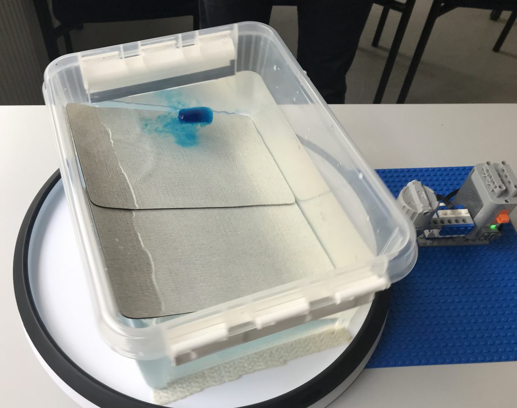
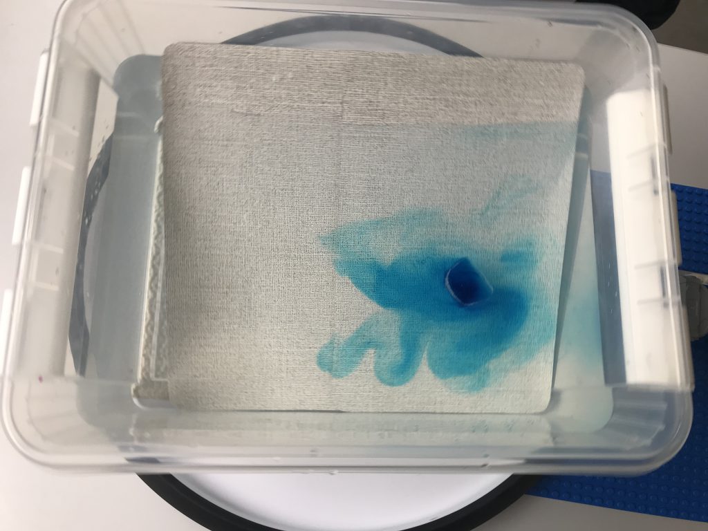
We are using the DIYnamics setup: A LEGO-driven Lazy Susan. And as a tank, we are using a transparent plastic storage box that I have had for many years, and the sloping bottom is made out of two breakfast boards that happened to be a good size.
Water is filled to “just below the edge of the white clips when they are in the lower position” (forgot to take measurements, this is seriously what I wrote down in my notes. We didn’t really think this experiment would work…)
The tank is then rotated at the LEGO motor’s speed (one rotation approximately every 3 seconds) and spun into solid body rotation. We waited for approximately 10 minutes, although I think we had reached solid body rotation a lot faster. But we had a lot of surface waves that were induced by some rotation that we couldn’t track down and fix. But in the end they turned out to not matter.
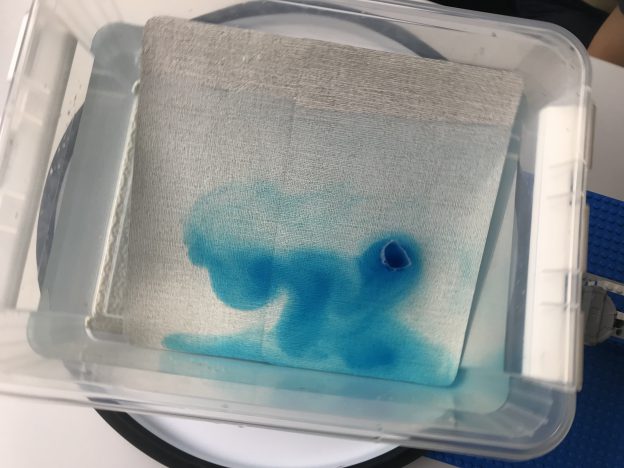
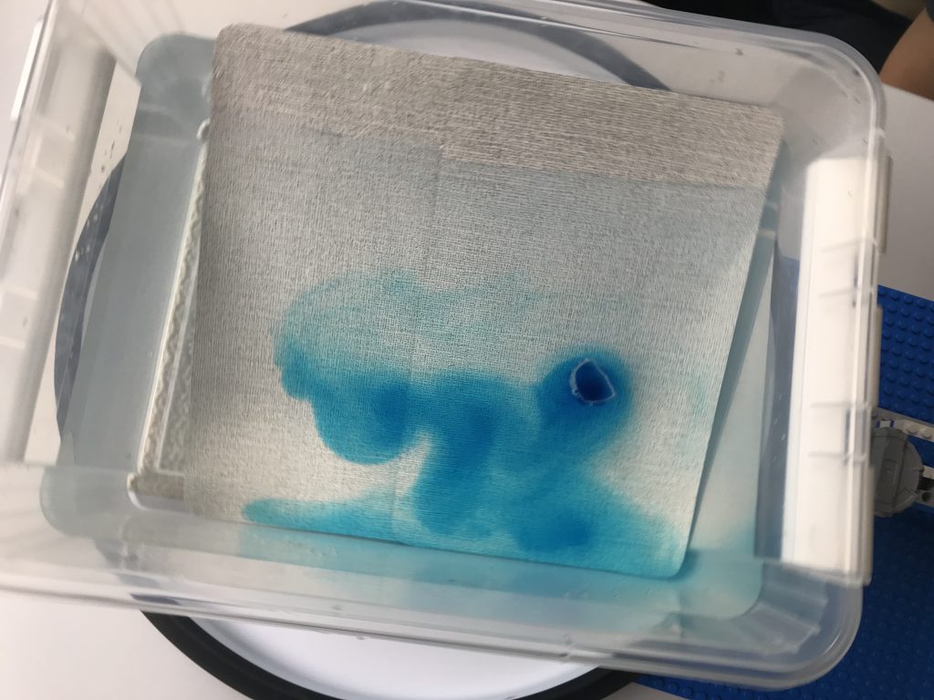
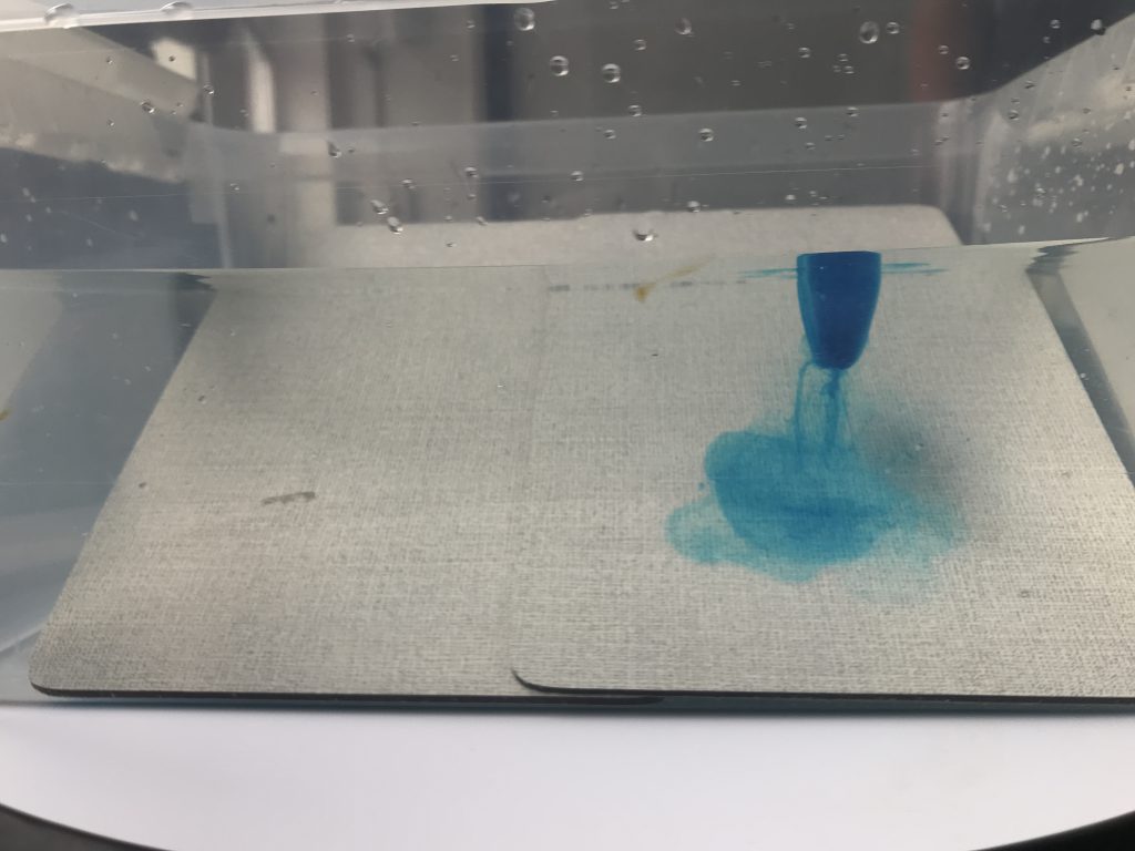
To start the experiment, Torge released a blue ice cube in the eastern corner of the shallow end. As the ice cube started melting, the cold melt water sank down towards the ground, where it started flowing towards the bottom of the tank. That increased the water column’s positive relative vorticity, which drove it back up the slope.
This was super cool to watch, especially since the ice cube started spinning cyclonically itself, too, so was moving in the same direction and faster than the rotating tank.
You see this rotation quite well in the movie below (if you manage to watch without getting seasick. We have a co-rotating setup coming up, it’s just not ready yet…)
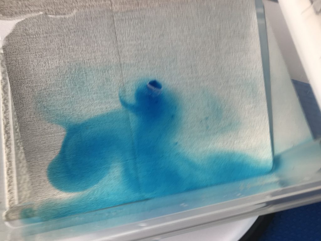
Very soon, these amazing meandering structures appear: Rossby waves! :-)
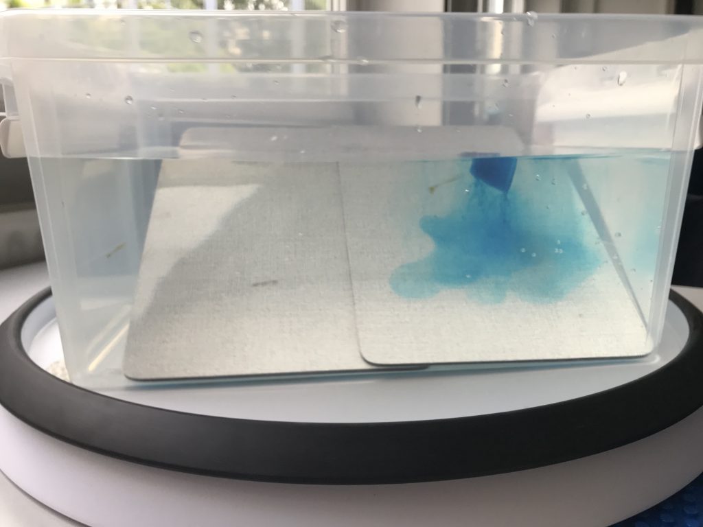
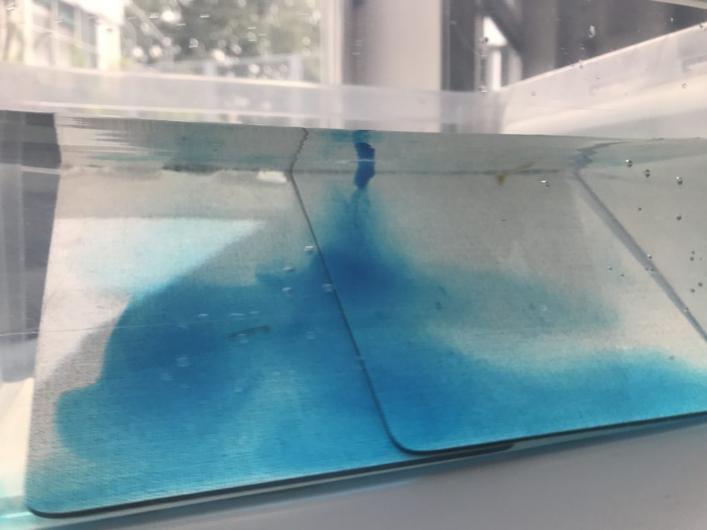
And over time it becomes clear that the eddies that are being shed from the column rotating with the ice cubes are constant throughout the whole water depth.
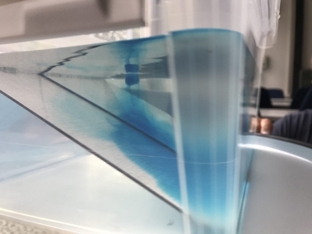
It is a little difficult to observe that the structure is really the same throughout the whole water column since the color in the eddies that were shed is very faint, especially compared to the ice cube and the melt water, but below you might be able to spot it for the big eddy on the left.
Or maybe here? (And note the surface waves that become visible in the reflection of the joint between the two breakfast boards that make up the sloping bottom. Why is there so much vibration in the system???)
You can definitely see the surface-to-bottom structures in the following movie if you don’t let yourself be distracted by a little #HamburgLove on the back of the breakfast boards. Watching this makes you feel really dizzy, and we’ve been starting at this for more than the 8 seconds of the clip below ;-)
After a while, the Taylor column with the ice cube floating on top starts visibly moving towards the west, too. See how it has almost reached the edge of the first breakfast board already?
And because this was so cool, we obviously had to repeat the experiment. New water, new ice cube.
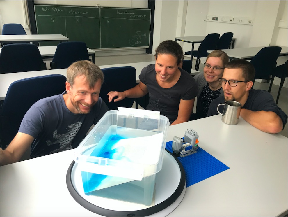
But: This time with an audience of excited oceanographers :-)
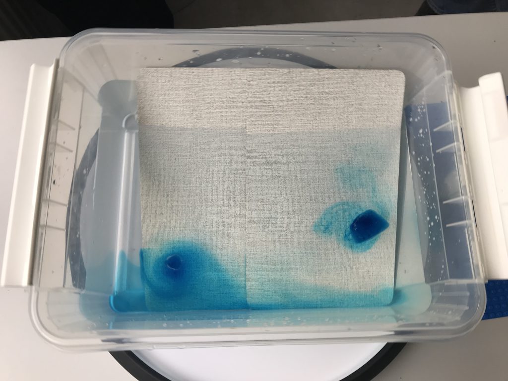
This time round, we also added a second ice cube after the first one had moved almost all the way towards the west (btw, do you see how that one has this really cool eddy around it, whereas the one in the east is only just starting to rotate and create its own Taylor column?)
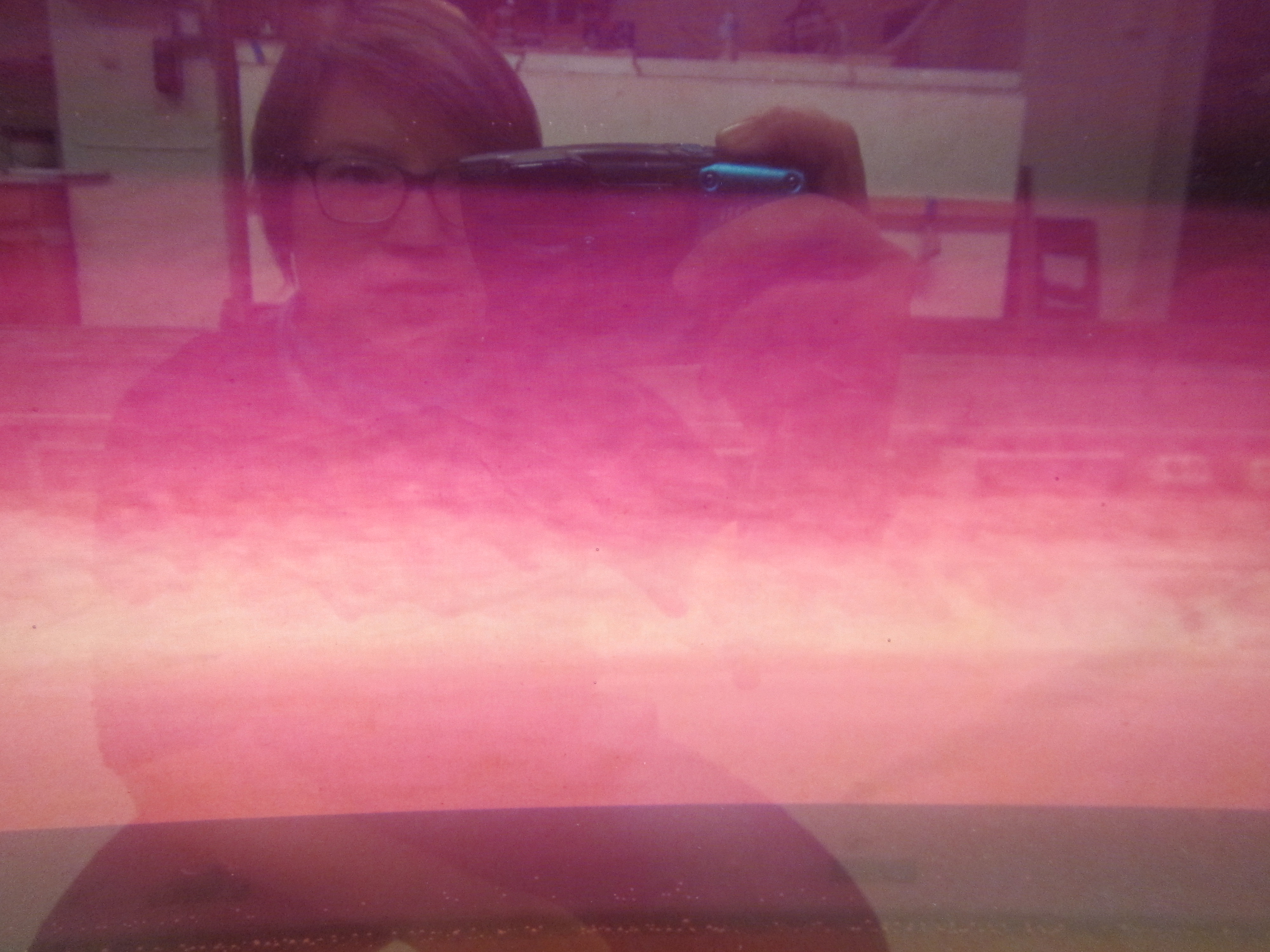
And last not least: Happy selfie because I realized that there are way too few pictures like this on my blog, where you see what things look like (in this case in the GEOMAR seminar room) and who I am playing with (left to right: Torge, Franzi, Joke, Jan) :-)
For both of my tank experiment projects, in Bergen and in Kiel, we want to develop a Rossby wave demonstration. So here are my notes on three setups we are considering, but before actually having tried any of the experiments.
Background on Rossby waves
I recently showed that rotating fluids behave fundamentally differently from non-rotating ones, in that they mainly occur in the horizontal and thus are “only” 2 dimensional. This works really well as long as several conditions are met, namely the water depth can’t change, nor can the rotation of the fluid. But this is not always the case, so when either the water depth or the rotation does change, the flow still tries to conserve potential vorticity and stay 2 dimensional, but now displays so-called Rossby waves.
Here are different setups for Rossby wave demonstrations I am currently considering.
Topographic Rossby wave
For a demonstration of topographic Rossby waves, we want the Coriolis parameter f to stay constant but have the depth H change. We use the instructions by geosci.uchicago.edu as inspiration for our experiment and
build a shallow ridge into the tank. They use an annulus and introduce the ridge at a random longitude, we could also build one across the center of the tank all the way to both sides to avoid weird things happening in the middle (or introduce a cylinder in the middle to mimic their annulus)
spin up the tank to approximately 26 rpm (that seems very fast! But that’s probably needed in order to create a parabolic surface with large height differences)
reduce rotation slightly, to approximately 23 rpm so the water inside the tank moves relative to the tank itself, and thus has to cross the ridge which is fixed to the tank
introduce dye upstream of the ridge, watch it change from laminar flow to eddies downstream of the ridge (they introduced dye at the inner wall of their annulus when the water was in solid body rotation, before slowing down the tank).
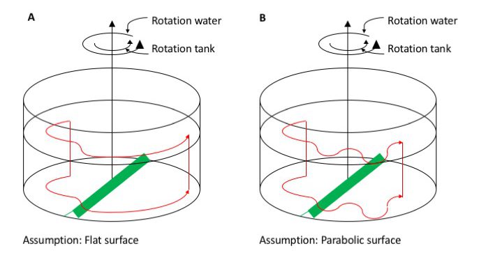
What are we expecting to see?
In case A, we assume that the rotation of the tank is slow enough that the surface is more or less flat. This will certainly not be the case if we rotate at 26rpm, but let’s discuss this case first, anyway. If we inject dye upstream of the obstacle, the dye will show that the current is being deflected as it crosses the ridge, to one direction as the water columns are getting shorter as they move up the ridge, then to the other direction when the columns are stretched going down the obstacle again. Afterwards, since the water depth stays constant, they would just resume a circular path.
In case B, however, we assume a parabolic surface of the tank, which we will have for any kind of fast-ish rotation. Initially, the current will move similarly to case A. But once it leaves the ridge, if it has any momentum in radial direction at all, it will overshoot its circular path, moving into water with a different depth. This will then again expand or compress the columns, inducing relative vorticity, leading to a meandering current and eddies downstream of the obstacle (probably a lot more chaotic than drawn in my sketch).
So in both cases we initially force the Rossby wave by topography at the bottom of the tank, but then in case B we sustain it by the changes in water depth due to the sloping surface.
My assessment before actually having run the experiment: The ridge seems fairly easy to construct and the experiment easy enough to run. However what I am worried about is the change in rotation rate and the turbulence and Ekman layers that it will introduce. After all, slowing down the tank is what we do create both turbulence and Ekman layers in demonstrations, and then we don’t even have an obstacle stuck in the tank. The instructions suggest a very slight reduction in rotation, so we’ll see how that goes…
Planetary Rossby waves on beta-plane
If we want to have more dramatic changes in water depth H than relying on the parabolic shape of the surface, another option is to use a rectangular tank and insert a sloping bottom as suggested by the Weather in a Tank group here. We are now operating on a Beta plane with the Coriolis parameter f being the sum of the tank’s rotation and the slope of the bottom.
fill a tank with a sloping bottom (slope approximately 0.5)
spin it at approximately 15 rpm until it reaches solid body rotation (15-20 minutes later)
place a dyed ice cube (diameter approximately 5 cm) in the north-eastern corner of the tank
What do we expect to see?
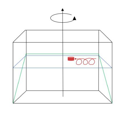
Ice cube and its trajectory (in red) on a sloping bottom in a rotating tank. Note: This sketch does not include the melt water water column!
Above is a simplified sketch of what will (hopefully!) happen. As the ice cube starts melting, melt water is going to sink down towards the sloping bottom, stretching the water column. This induces positive relative vorticity, making the water column spin cyclonically. As the meltwater reaches the sloping bottom, it will flow downhill, further stretching the water column. This induces more positive relative vorticity still, so the water column, and with it the ice cube, will start moving back up the slope until they reach the “latitude” at which the ice cube initially started. Having moved up the slope into shallower water, the additional positive vorticity induced by the stretching as the water was flowing down the slope has now been lost again, so rather than spinning cyclonically in one spot, the trajectory is an extended cycloid.
My assessment here (before having run it): I find this experiment a little more unintuitive because there are the different components of stretching contributing to the changes in relative vorticity. And from the videos I’ve seen, we don’t really get a clear column moving, but there are cyclonic eddies in the boundary layer that are shed. So I think this might be more difficult to observe and interpret. But I am excited to try!
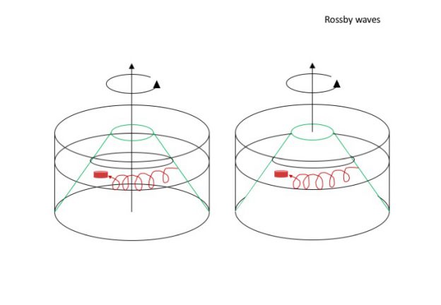
Planetary Rossby wave on a cone (cyclical beta-plane?)
Following the Weather in a Tank instructions, we plan to also do the experiment as above but with cyclical boundary conditions, by using a cone in a cylindrical tank instead of a sloping bottom in a rectangular one.
The experiment is run in the same way as the one above (except they suggest a slightly slower rotation of 10 rpm). Physics are the same as before, except that now the transfer to reality should be a little easier, since we now have Rossby waves that can really run all the way around the pole. Also the experiment can be run for a longer time, since we don’t run into a boundary in the west if we are moving around and around the pole.
Ice cube and its trajectory (in red) on a cone in a rotating tank. Note: This sketch does not include the melt water column!
My assessment before actually having run the experiment: This shouldn’t be any more difficult to run, observe or interpret than the one above (at least once we’ve gotten our hands on a cone). Definitely want to try this!
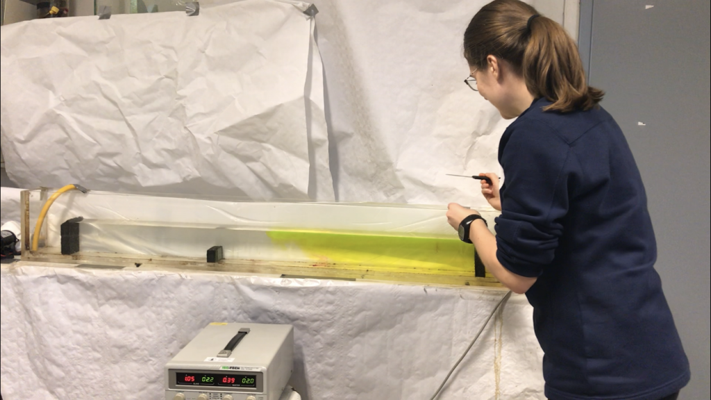
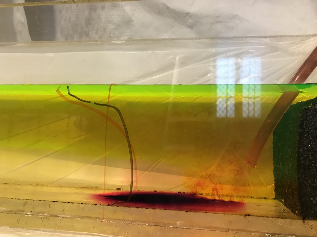
It has been a long time in the making, but finally we have a nice fjord circulation in our tank!
Pierre and I tried to improve it 6 years ago, Steffi, Ailin and I have been working on it for a couple of days last August, then finally this morning, Steffi and I tried again — and it worked beautifully right away!
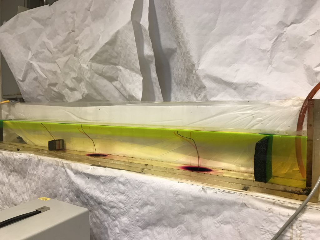
We now have an experiment that shows how a fresh, yellow inflow (representing the freshwater input into fjords close to their heads by rivers) flows over a initially stagnant pool of salt water. As the freshwater plume flows out of the fjord, it entrains more and more salt water from below, thus thickening and setting up a return flow that brings in more salt water from the reservoir (representing the open ocean) on the right.
We drop dye crystals to visualize the surface current going out of the fjord and the return flow going in, and draw the profiles on the tank to be able to discuss them later.
Here is a movie of the whole thing:
But there is more to see!
When tipping the tank to empty it, a lot of turbulence was created at the sill (see movie below). While a fjord typically isn’t tipped very often, what we see here is basically what tides do on the sill (see the waves that keep going back and forth over the sill after the tank is initially lifted? Those are exactly like tides). This could purposefully integrated in teaching rather than only happen by accident, those waves could be created just by surface forcing rather than by tipping the tank. That’s a very nice demonstration to explain high mixing rates in the vicinity of steep topography!
And then there is also the issue of very low oxygen concentrations in some Norwegian fjords, and one proposed solution is to bring the river inflow deep down into the fjord. The idea is that the less dense river water will move up to the surface again, thereby creating mixing and oxygenating the stagnant deep water that, in some cases, hasn’t been renewed in many years.
We model this by putting the inflow (the hose) down into the tank and see the expected behaviour. What we also see: Since the water has a quite strong downward component as it enters the fjord, it stirs up a lot of old dye from the bottom. So possibly something to be aware of since there might be stuff dumped into fjords that you might not necessarily want to stir up…
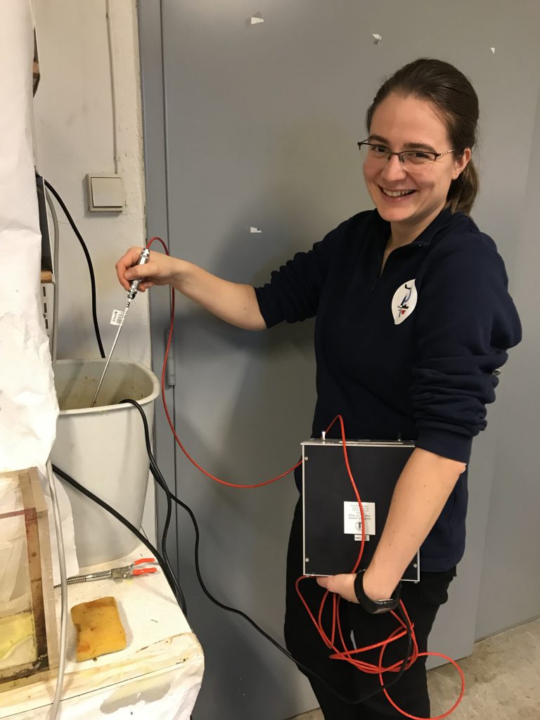
And last, not least, a bonus picture: This is how we measure temperature at GFI. You would think it should be possible to find a smaller thermometer that isn’t an old reversing mercury one? But in any case, this worked very well, too :-)
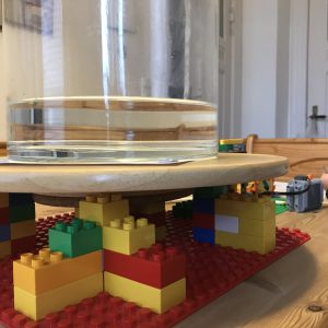
Turns out building a rotating table isn’t as easy as we had hoped, because my Lazy Susan’s axle is unfortunately really off centre (how did I never notice before?), which makes it pretty difficult to drive it with a grinding wheel, and the LEGO motor we were using only has one speed (which would have to be regulated by changing the diameter of the gears). That makes it really difficult to spin up a tank at rest if you go at it zero to full force…
But we got it to spin! Look at the cool paraboloid surface!
Next issue, though: my awesome glass vase which looks like it should work well as a tank has a really irregular bottom, which makes it very difficult to have anything stand in the centre without too much of a wobble. Also, for the Hadley Circulation experiment we were trying to set up here, when do you add in the cooling in the center? Would be best to do it after the tank is spun up, but that is such a pain to do! And I messed up the dye here, too.
But at least you can see a little bit of what it will be like when we are done, right?
Next time:
better Lazy Susan
better lighting
think about how to film it, therefore either have a co-rotating camera or a white background
And then it will be almost ready to be used in teaching. Well, almost…
Funny how tank experiments that you think should be quick and easy to set up & run always take sooo much longer than expected. But it’s so much fun that I really don’t mind! :-)
I’d love your input: If your student lab for GFD tank experiments had to downsize, but you had to present a “wish list” for a smaller replacement, what would be on that list? Below are my considerations, but I would be super grateful for any additional input or comments! :-)
Background and “boundary conditions”
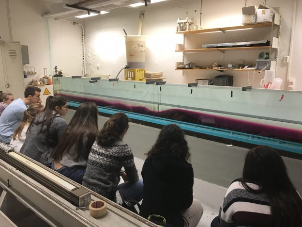
The awesome towing tank that you have come to love (see picture above) will have to be removed to make room for a new cantina. It might get moved into a smaller room, or possibly replaced all together. Here are some external requirements, as far as I am aware of them:
the (new) tank should ideally be movable so the (small) room can be used multi-purpose
since the new room is fairly small, people would be happy if the new tank was also smaller than the old one
the rotating table is kept (and a second, smaller one, exists in the building)
There are other, smaller tanks that will be kept for other experiments, dimensions approximately 175x15x40cm and smaller
the whole proposal needs to be inexpensive enough so that the likelyhood that it will actually be approved is moderate to fair ;-)
Here are a couple of things I think need to be definitely considered.
Dimensions of the tank
If the tank was to be replaced by a smaller one, how small could the smaller one be?
The dimension of the new tank depend, of course, on the type of experiment that should be done in the tank. Experiments that I have run in the tank that is to be replaced and that in my opinion should definitely be made possible in the new location/tank include
“Dead water”, where a ship creates internal waves on a density interface (instructions)
Internal lee waves & hydraulic jumps, where a mountain is moved at the bottom of the tank (instructions)
Surface waves running up on a slope (I haven’t blogged about that yet, movies waiting to be edited)
If we want to be able to continue running these experiments, here is why we should not sacrifice the dimensions of the tank.
Why we need the tank length
The first reason for keeping the length of the tank is that the “mountains” being towed to create the lee waves are already 1 and 1.5m long, respectively. This is a length that is “lost” for actual experiments, because obviously the mountain needs space inside the tank on either end (so in its start and end position). Additionally, when the mountain starts to move, it has to move for some distance before the flow starts displaying the features we want to present: Initially, there is no reservoir on the “upstream” side of the mountain and it only builds up over the first half meter or so.
The second reason for keeping the length of the tank are wave reflections once the ship or mountain comes close to the other side of the tank. Reflected surface waves running against the ship will set up additional drag that we don’t want when we are focussing on the interaction between the ship and the internal wave field. Reflected internal waves similarly mess things up in both experiments
The third reason for keeping the length of the tank is its purpose: as teaching tank. Even if one might get away with a slightly shorter tank for experiments when you just film and investigate the short stretch in the middle of the tank where there are no issues with either the push you gave the system when starting the experiment or the reflections when you get near the end, the whole purpose of the tank is to have students observe. This means that there needs to be a good amount of time where the phenomenon in question is actually present and observable, which, for the tank, means that it has to be as long as possible.
Why we need the tank width
In the experiments mentioned above, with exception of the “dead water” experiment, the tank represents a “slice” of the ocean. We are not interested in changes across the width of the tank, and therefore it does not need to be very wide. However, if there is water moving inside the tank, there will be friction with the side walls and the thinner the tank, the more important the influence of that friction will become. If you look for example at the surface imprint of internal wave experiment, you do see that the flow is slowed down on either side. So if you want flow that is outside of the boundary layers on either side, you need to keep some width.
Secondly, not changing the tank’s width has the advantage that no new mountains/ships need to be built.
Another, practical argument for a wide-ish tank (that I feel VERY strongly about) is that the tank will need to be cleaned. Not just rinsed with water, but scrubbed with a sponge. And I have had my hands inside enough tanks to appreciate if the tank is wide enough that my arm does not have to touch both sides at all times when reaching in to clean the tank.
Why we need the tank depth
The first reason for keeping the height is that for the “dead water” experiment, even the existing tank is a lot shallower than what we’d like from theory (more here). If we go shallower, at some point the interactions between the internal waves and the ground will become so large that it will mess up everything.
Another reason for keeping the depth is the “waves running up a slope” experiment. If you want waves running up a slope (and building up in height as they do), you have the choice between high walls of the tank or water spilling. Just sayin’…
And last not least: this tank has been used in “actual” research (rather than just teaching demonstrations, more on that on Elin’s blog), so if nothing else, those guys will have thought long and hard about what they need before building the tank…
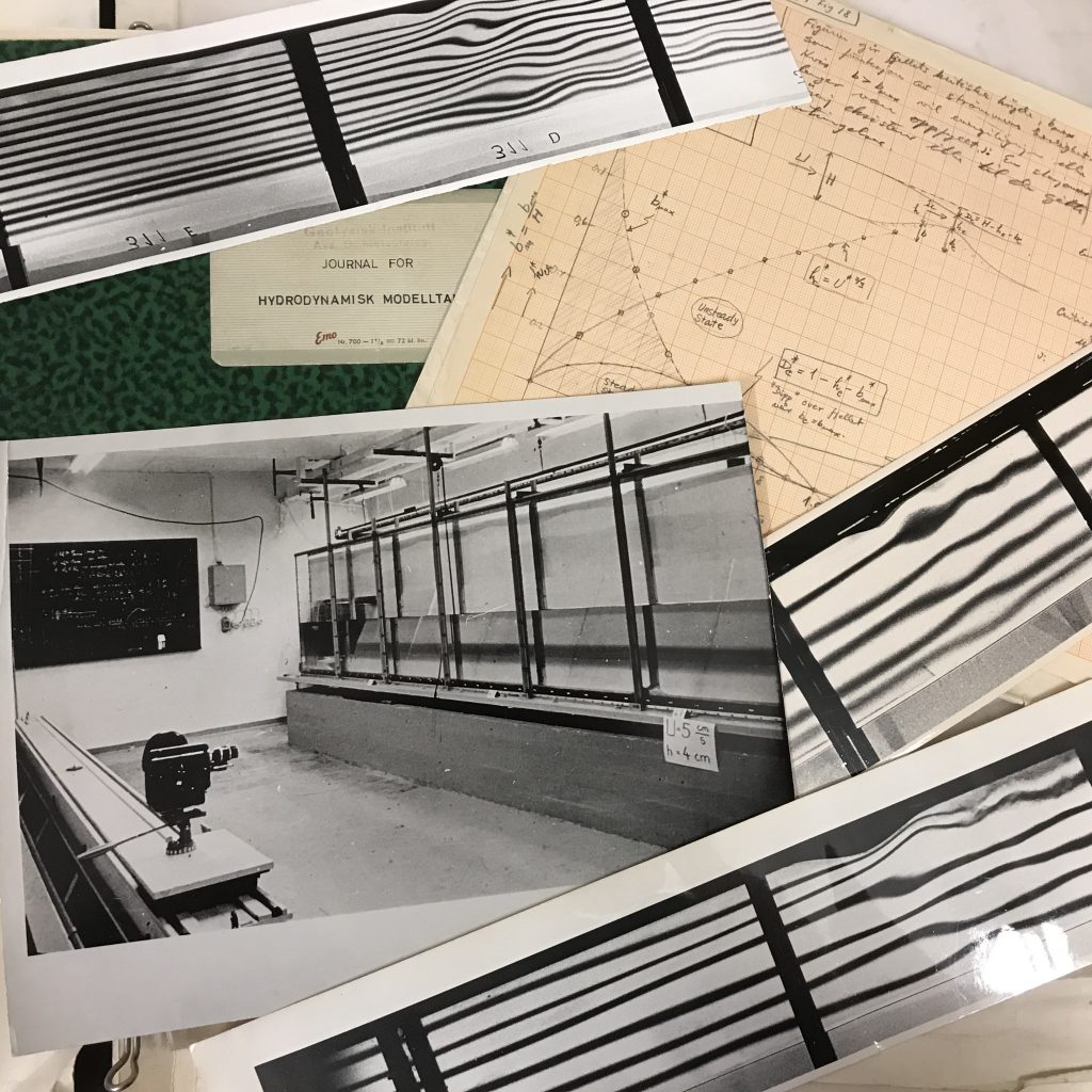
Historical images of research on internal lee waves being done with the tank
Without getting too philosophical here about models and what they can and cannot achieve (and tank experiments being models of phenomena in the ocean), the problem is that scaling of the ocean into a tiny tank does not work, so “just use a mountain/boat half the size of the existing ones!” is actually not possible. Similarly to how if you build the most amazing model train landscape, at some point you will decide that tiny white dots are accurate enough representations of daisies on a lawn, if you go to a certain size, the tank will not be able to display everything you want to see. So going smaller and smaller and smaller just does not work. A more in-depth and scientific discussion of the issue here.
Other features of the tank
When building a new tank or setting up the existing tank in a new spot, there are some features that I consider to be important:
The tank needs a white, intransparent back wall (either permanently or draped with something) so that students can easily focus on what is going on inside the tank. Tank experiments are difficult to observe and even more difficult to take pictures of, the better the contrast against a calm background, the better
The tank should be made of glass or some other material that can get scrubbed without scratching the surface. Even if there is only tap water in the tank, it’s incredible how dirty tanks get and how hard they have to be scrubbed to get clean again!
The tank needs plenty of inlets for source waters to allow for many different uses. With the current tank, I have mainly used an inlet through the bottom to set up stratifications, because it allowed for careful layering “from below”. But sometimes it would be very convenient to have inlets from the side close to the bottom, too. And yes, a hose could also be lowered into the tank to have water flow in near the bottom, but then there needs to be some type of construction on which a hose can be mounted so it stays in one place and does not move.
There needs to be scaffolding above the tank, and it needs to be easily modifiable to mount cameras, pulleys, lights, …
We need mechanism to tow mountains and ships. The current tank has two different mechanisms set up, one for mountains, one for ships. While the one for the ship is home-made and easily reproducible in a different setting (instructions), the one to tow the mountain with is not. If there was a new mechanism built, one would need to make sure the speeds at which the mountain can be towed matches the internal wave speed to be used in the experiment, which depends on the stratification. This is easy enough to calculate, but it needs to be done before anything is built. And the mechanism does require very securely installed pulleys at the bottom of the tank which need to be considered and planned for right from the start.
“Source” reservoirs
The “source” reservoirs (plural!) are the reservoirs in which water is prepared before the tank is filled. It is crucial that water can be prepared in advance; mixing water inside the tank is not feasible.
There should be two source reservoirs, each large enough to carry half the volume of the tank. This way, good stratifications can be set up easily (see here for how that works. Of course it works also with smaller reservoirs in which you prepare water in batches as you see below. But what can happen then is that you don’t get the water properties exactly right and you end up seeing stuff you did not want to see, as for example here, which can mess up your whole experiment)
Both reservoirs should sit above the height of the tank so that the water can be driven into the tank by gravity (yes, pumps could work, too, more on that below).
“Sink” reservoir
Depending on the kind of dyes and tracer used in the water, the water will need to be collected and disposed of rather than just being poured down the drain. The reservoir that catches the “waste” water needs to
be able to hold the whole volume of the tank
sit lower than the tank so gravity will empty the tank into the reservoir (or there needs to be a fast pump to empty the tank, more on that below)
be able to be either transported out of the room and the building (which means that doors have to be wide enough, no steps on the way out, …) or there needs to be a way to empty out the reservoir, too
be able to either easily be replaced by an empty one, or there needs to be some kind of mechanism for who empties it within a couple of hours of it being filled, so that the next experiment can be run and emptied out
If the waste water is just plain clear tap water, it can be reused for future experiments. In this case, it can be stored and there need to be…
Pumps
If reservoirs cannot be located above and below tank height to use gravity to fill and empty the tanks, we need pumps (plural).
A fast pump to empty out the tank into the sink reservoir, which can also be used to recycle the water from the sink reservoir into the source reservoirs
One pump that can be regulated very precisely even at low flow rates to set the inflow into the tank
Preferable the first and the latter are not the same, because changing settings between calibrating the pump for an experiment, setting it on full power to empty the tank, and calibrating it again will cause a lot of extra work.
Inlets for dyes
Sometimes it would be extremely convenient if there was a possibility to insert dyes into the tank for short, distinct periods of time during filling to mark different layers. For this, it would be great to be able to connect syringes to the inlet
Hoses and adapters
I’ve worked for years with whatever hoses I could find, and tons of different adapters to connect the hoses to my reservoir, the tap, the tank. It would be so much less of a hassle if someone thought through which hoses will actually be needed, bought them at the right diameter and length, and outfitted them with the adapters they needed to work.
Space to run the experiment
The tank needs to be accessible from the back side so the experimenter can run the experiment without walking in front of the observers (since the whole purpose of the tank is to be observed by students). The experimenter also needs to be able to get out from behind the tank without a hassle so he or she can point out features of interest on the other side.
Also, very importantly, the experimenter needs to be able to reach taps very quickly (without squeezing through a tight gap or climbing over something) in case hoses come loose, or the emergency stop for any mechanism pulling mountains in case something goes wrong there.
Space for observers
There needs to be enough room to have a class of 25ish students plus ideally a handful of other interested people in the room. But not only do they need to fit into the room, they also need to be able to see the experiments (they should not have to stand in several rows behind each other, so all the small people in the back get to see are the shoulders of the people in front). Ideally, there will be space so they can duck down to have their eyes at the same height as the features of interest (e.g. the density interface). If the students don’t have the chance to observe, there is no point of running an experiment in the first place.
Filming
Ideally, when designing the layout of the room, it is considered how tank experiments will be documented, i.e. most likely filmed, and there needs to be space at a sufficient distance from the tank to set up a tripod etc..
Lighting
Both for direct observations and for students observing tank experiments, it is crucial that the lighting in the room has been carefully planned so there are minimal reflections on the walls of the tank and students are not blinded by light coming through the back of the tank if a backlighting solution is chosen.
Summary
In my experience, even though many instructors are extremely interested in having their students observe experiments, there are not many people willing to run tank experiments of the scale we are talking about here in their teaching. This is because there is a lot of work involved in setting up those experiments, running them, and cleaning up afterwards. Also there are a lot of fears of experiments “going wrong” and instructors then having to react to unexpected observations. Running tank experiments requires considerable skill and experience. So if we want people using the new room and new tank at all, this has to be made as easy as possible for them. Therefore I would highly recommend that someone with expertise in setting up and running experiments, and using them in teaching, gets involved in designing and setting up the new room. And I’d definitely be willing to be that person. Just sayin’ ;-)
How will lee waves look differently if we are using the asymmetrical mountain instead of the symmetric one? And is symmetry actually important at all or are we just looking at different slopes downstream while the upstream slope doesn’t have an influence on the wave field?
There are a couple of reasons why I had not done that before:
It’s longer (1.5 m instead of the 1 m of the other mountain), therefore the tank is, relatively speaking, shorter. And since being close to the ends of the tank leads to weird interferences, this limits the distance over which observations can be made
Since it’s asymmetrical, pulling one way or the other would likely show different wave fields, so you couldn’t just run it back and forth and have students observe the same thing several times in a row
But then it would be really interesting to see what the difference would be, right?
I tried two different stratifications.
Weak stratification, shallow water
Since I just wanted a quick idea of what this mountain would do, I used leftover water I had prepared for the moving mountain experiment. Since there wasn’t a lot left, I ended up with 11.5 cm fresh water, but only 4 cm salt water at approximately 20 psu (since I stretched the 35 psu a little).
What I noticed: A LOT more mixing than with the other mountain! Stratification is pretty much destroyed after the first run, usually we run back and forth a lot. This can be for several reasons:
The water is very shallow, meaning mixing is happening over the whole water column. It might not actually be more mixing than in the other case, but since it’s affecting the whole water column, it might just seem like more because no clearly visible stratification is left above and below the layer which is mixed by the mountain?
The left side of the mountain was bent up a little (as in 2 or 3 cm), meaning that especially on the way back it was flapping up and down on the upstream side, doing a lot of mixing that wasn’t due to the shape of the mountain, just of bits of it being loose.
And the shape of the “reservoir” that is being built up upstream of the mountain is different to what I have observed before: Running in either direction, the reservoir didn’t built up smoothly, but as a hump that was pushed in front of the mountain. Maybe because the internal wave speed in this case was very close to the speed of the mountain, something like 7cm/s, so the disturbance created by the mountain couldn’t propagate upstream. Is that an upstream hydraulic jump we are seeing there?!
Since I was not satisfied with this at all, I ran a second experiment:
Strong stratification, deep water
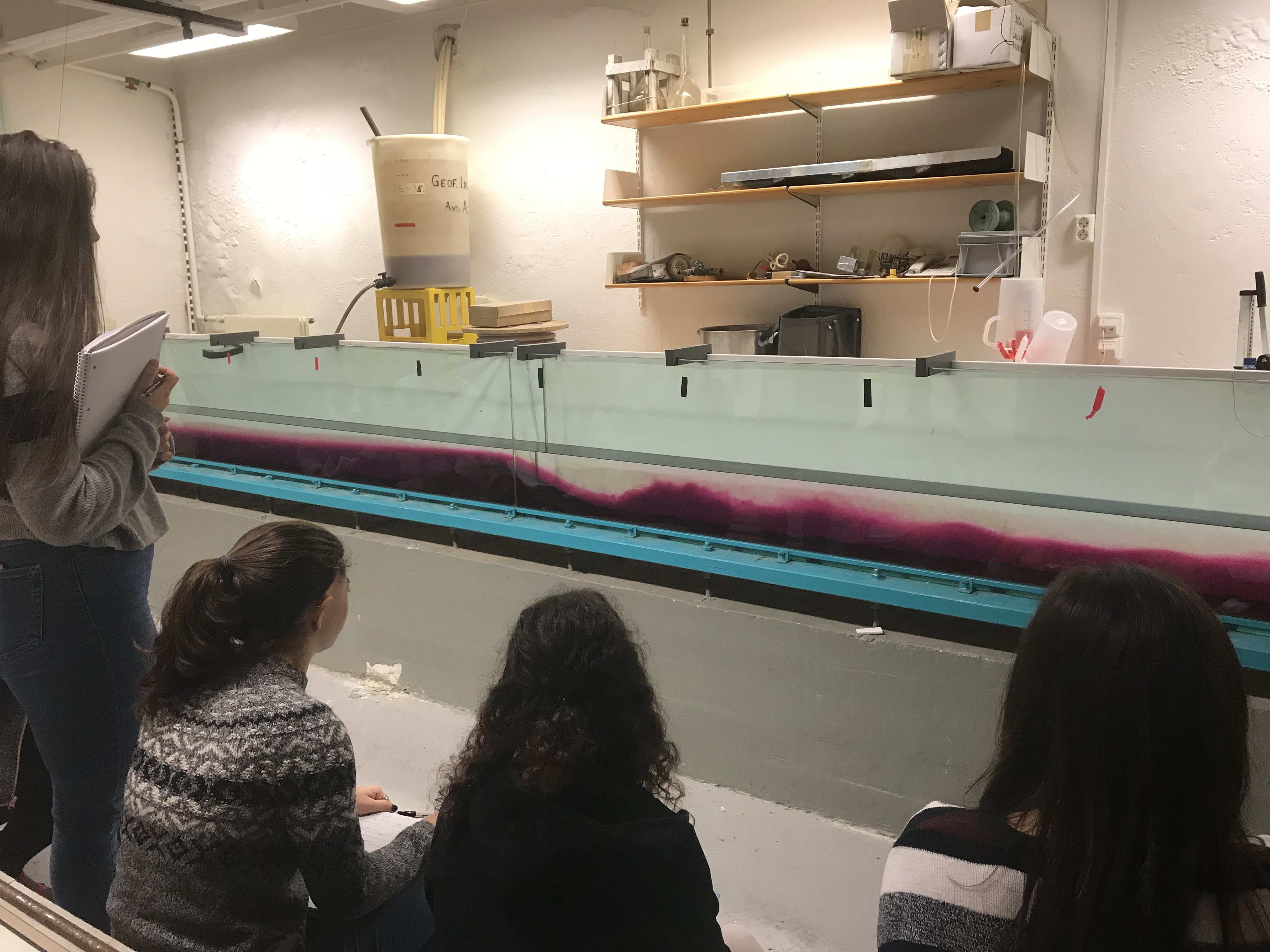
First, I tried to set up the same stratification as for this lee wave experiment with the symmetrical mountain because I thought that would be easiest to compare. But I aborted that after having moved the mountain just a little because it was mixing so much that there stratification was destroyed completely and nothing could be seen. I ended up putting more dense water in and ended up with 12 cm pink (35 psu) and 4 cm clear freshwater. And this is what this looked like:
You now see a wave train with wave lengths longer than in the symmetrical case. Probably due to the longer length of the obstacle (even thought the waves are still shorter than the obstacle)? Or what sets the wavelength?
This time, with a faster internal wave speed of around 10cm/s while the mountain is still pulled with 7cm/s, we don’t see the “hump” in the upstream reservoir — the signal can propagate faster than the mountain and thus smoothes out.
So that is what I think is going on here. While the first experiment mainly showed effects of the stratification compared to previous experiments, the second one might provide some insight on the different slopes of the mountain, although I am not sure in what way. Do you see something I didn’t observe? How would you expect the different slopes to influence the lee waves?
I am so glad I tried this and I’m looking forward to thinking about this more! :-) Any insights you’d care to share with me?
This blog post is meant as guideline if someone other than me might have to set up this demonstration at some point… Have fun! :-)
Lee waves
Lee waves are the kind of waves that can be observed downwind of a mountain in the clouds, or downstream of an obstacle in a current as a series of undulations with crests parallel to the disturbance.
Why move the mountain?
Students sometimes find it hard to imagine that a moving mountain should be equivalent to flow across a ridge. It helps to discuss how it would be really difficult to set up a flow in a tank: A huge amount of water would need to be moved without too much turbulence. Instead, it’s a lot easier to imagine the water is moving by moving a mountain through the tank, so the water is moving relative to it if not relative to the lab.
Dimensions
The size of the tank is 60×1.5×5 dm, so it can hold a total of 450l of water.
The mountain we use is 10.5 cm high and 1 m long and it’s symmetric, so pulling it either way shows similar lee waves (which is why I’ve always used it). There is a second, asymmetrical mountain on the shelf that I have never used*.
Setting up the stratification
The stratification that we’ve found works well is 10 cm at 35 psu (here dyed pink) and 9 cm at 0 psu. This leads to an internal wave speed of approximately ~11cm/s.
Prepare the dense water in a barrel that sits high enough so gravity will bring the water down into the tank (see picture below). For the 80l barrel, you need 2.8kg of salt and 1/3 tea spoon of dye MAX.
Elin’s GEOF213 class observing lee waves
You achieve the stratification by filling in the fresh water first through the bottom left inlet, moving the mountain over it, and filling in the dense water. That way the mixing is contained to the volume underneath the mountain which will be a lot better for your nerves (believe me!).
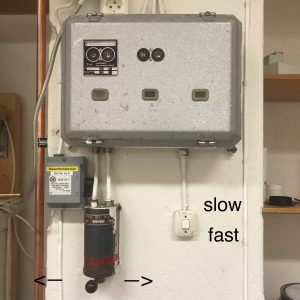
Moving the mountain
The system that pulls the mountain can go at two speeds: “fast” and “slow”, “slow” meaning 5m in 1:11min (7cm/s) and “fast” meaning 5m in 0:36min (14cm/s).
Here is where you run the mountain from:
Troubleshooting if the mountain doesn’t move:
you might be trying to pull the mountain in the wrong direction (into the wall)
the mountain might not be located on the sledge well. There is a tongue on the sledge that needs to sit in the groove in the mountain
the mountain might not be sitting well in the tank so an edge digs into the side
the belt that pulls the tank might not be tight enough (always make sure the two weights at both ends of the tank are actually hanging down to put tension on the belt!)
the belt might have come off the axle that drives it (the white plastic above the left end of the tank)
Elin’s GEOF213 class observing lee waves
Observations
As you see in the pictures above (or the movie below), there is a lot to observe!
Lee waves (not one, but a whole train!)
Different flow regimes: supercritical shooting down the lee side of the mountain, then a hydraulic jump, and then a normal flow
The reservoir upstream of the mountain that builds up as the mountain is moving
Even after the mountain has stopped, you see waves travelling through the tank and being reflected at the ends
Turbulence!
Movie
Here is a movie of the lee wave experiment. Feel free to use it in teaching if you like! And let me know if you need the movie in a higher resolution, I am happy to share!
*Yes, this was true at the time of writing. But I am setting up that experiment as we speak. Write. Read. Whatever. Will post movies tomorrow!
When setting up the stratification for the Nansen “dead water” demo (that we’ll show later today, and until then I am not allowed to share any videos, sorry!), I went into a meeting after filling in layer 4 (the then lowest). When I came back, I wanted to fill in layer 5 as the new bottom layer. For this experiment we want the bottom four layers to have the same density (so we would actually only have one shallow top layer and then a deep layer below [but we can’t make enough salt water at a time for that layer, so I had to split it into four portions]), and I had mixed it as well as I could. But two things happened: a) my salinity was clearly a little fresher than the previous layer, and b) the water in the tank had warmed up and the new water I was adding with layer 5 was cold tap water. So I accidentally set up the stratification for salt fingering: warm and salty over cold and fresh! Can you spot the darker pink fingers reaching down into the slightly lighter pink water? How cool is this??? I am completely flashed. Salt fingering in a 6 meter long tank! :-D
So you thought filling water into a tank was boring? Not on my watch!
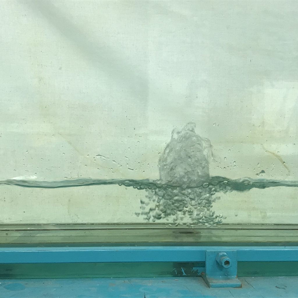
This is how we fill up the tank: Through a hole at the bottom. Which leads to a very nice fountain that slowly submerges as the water level rises:
…and to tons of nice waves, which are great to observe!
Propagation of waves
Below you see waves propagating. Can you spot the water’s orbital movement, i.e. water particles moving in circles, even though the wave phase is propagating from left to right?
Standing waves
After a while, waves are reflected at the end of the tank and propagate back, setting up a different, very cool, pattern:
Now the wave phase does not seem to travel any more! Instead, there are fixed points in space where water levels oscillate between maximum and minimum, and in between there are other points where the water level stays more or less the same. How cool is that?!
…And this is just filling the tank. Just wait how cool it gets when we are actually running our demonstrations! :-)
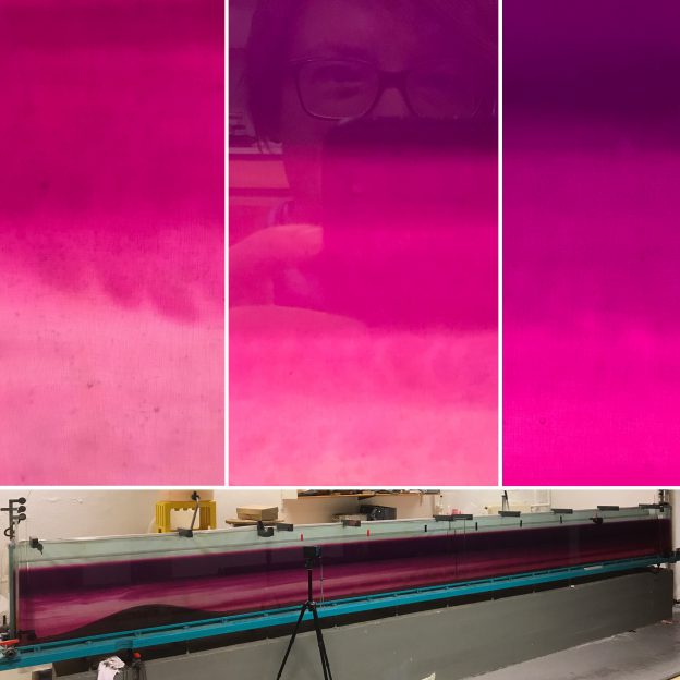
My favorite oceanographic process, as all of my students and many of my acquaintances know, is double-diffusive mixing. Look at how awesome it is:
Double-diffusive mixing happens because heat and salt’s molecular diffusion are very different: Heat diffuses about a factor 100 faster than salt. This can lead to curious phenomena: Bodies of water with a stable stratification in density will start to mix much more efficiently than one would have thought.
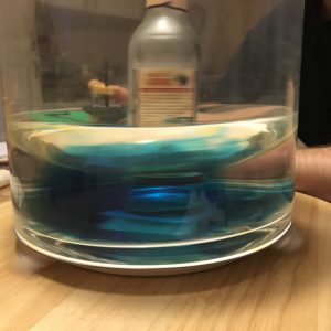
In the specific case of a stable density stratification with warm, salty water over cold, fresh water, finger-like structures form. Those structures are called “salt fingers”, the process is “salt fingering”.
Salt fingering occuring with the red food dye acting as “salt”.
Even though salt fingers are tiny compared to the dimensions of the ocean, they still have a measurable effect on the oceanic stratification in the form of large-scale layers and stair cases, and not only the stratification in temperature and salinity, but also on nutrient availability in the subtropical gyres, for example, or on CO2 drawdown.
Over the next couple of posts, I will focus on double diffusive mixing, but less on the science and more on how it can be used in teaching. (If you want to know more about the science, there are tons of interesting papers around, for example my very first paper)
How to easily set up the stratification for the salt fingering process.
Setting up stratifications in tanks is a pain. Of course there are sophisticated methods, but when you want to just quickly set something up in class (or in your own kitchen) you don’t necessarily want to go through the whole hassle of a proper lab setup.
For double diffusive mixing, there are several methods out there that people routinely use.
For example the hose-and-funnel technique, where the less dense fluid is filled in the tank first and then the denser fluid is slid underneath with the help of a hose and a funnel. And a diffuser at the end of the hose. And careful pouring. And usually a lot more mixing than desired.
Or the plastic-wrap-to-prevent-mixing technique, where the dense fluid is put into the tank, covered by plastic wrap, and then the lighter fluid is poured on top. Then the plastic wrap is removed and by doing so the stratification is being destroyed. (No video because I was frustrated and deleted it right away)
Or some other techniques that I tried and didn’t find too impressive. (No videos either for the same reason as above)
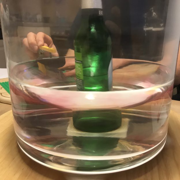
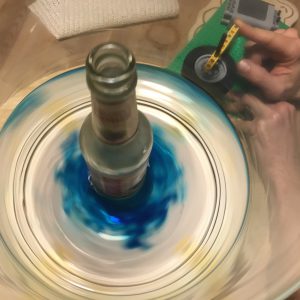
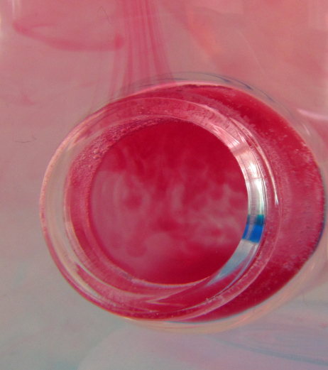
But then accidentally I came across this method (as in: I wanted to show something completely different, but then I saw the salt fingers and was hooked):
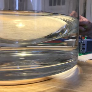
Granted, this is not a realistic model of an oceanic stratification. But as you can see towards the end of that movie, that turns out to be a blessing in disguise if you want to talk about the process in detail. As you see in the movie, the salt fingers inside the bottle are much smaller than the salt fingers outside the bottle. Because, clearly, inside the bottle the warm water is cooled both at the interface with the cold water inside the bottle, and by heat conduction through the walls of the bottle, since the water is surrounded by cold water. The warm water that flowed out of the bottle and up towards the water’s surface is only cooled at the interface with the water below (the air above is warmer than the cold water). So this gives you the perfect opportunity to discuss the scaling of salt fingers depending on the stratification without having to go through the pains of actually preparing stratifications with different gradients in temperature or salinity.
Self-portrait with salt fingers :-)
In my experience, the best salt fingers happen when you use hot water with dye (as the warm and salty top layer) and cold fresh water below. Salt fingers develop quickly, you don’t have the hassle of hitting the exact temperatures or salinities to make the density stratification statically stable, yet unstable in salinity, and it ALWAYS works.
Double-diffusive mixing. Scale at the bottom is centimeters.
Salt fingering in a tank. Scale at the bottom is centimeters.
And look at how beautiful it looks! Do you understand why I LOVE double diffusion?
—
P.S.: This text originally appeared on my website as a page. Due to upcoming restructuring of this website, I am reposting it as a blog post. This is the original version last modified on November 4th, 2015.
I might write things differently if I was writing them now, but I still like to keep my blog as archive of my thoughts.