Tag Archives: GEOF105

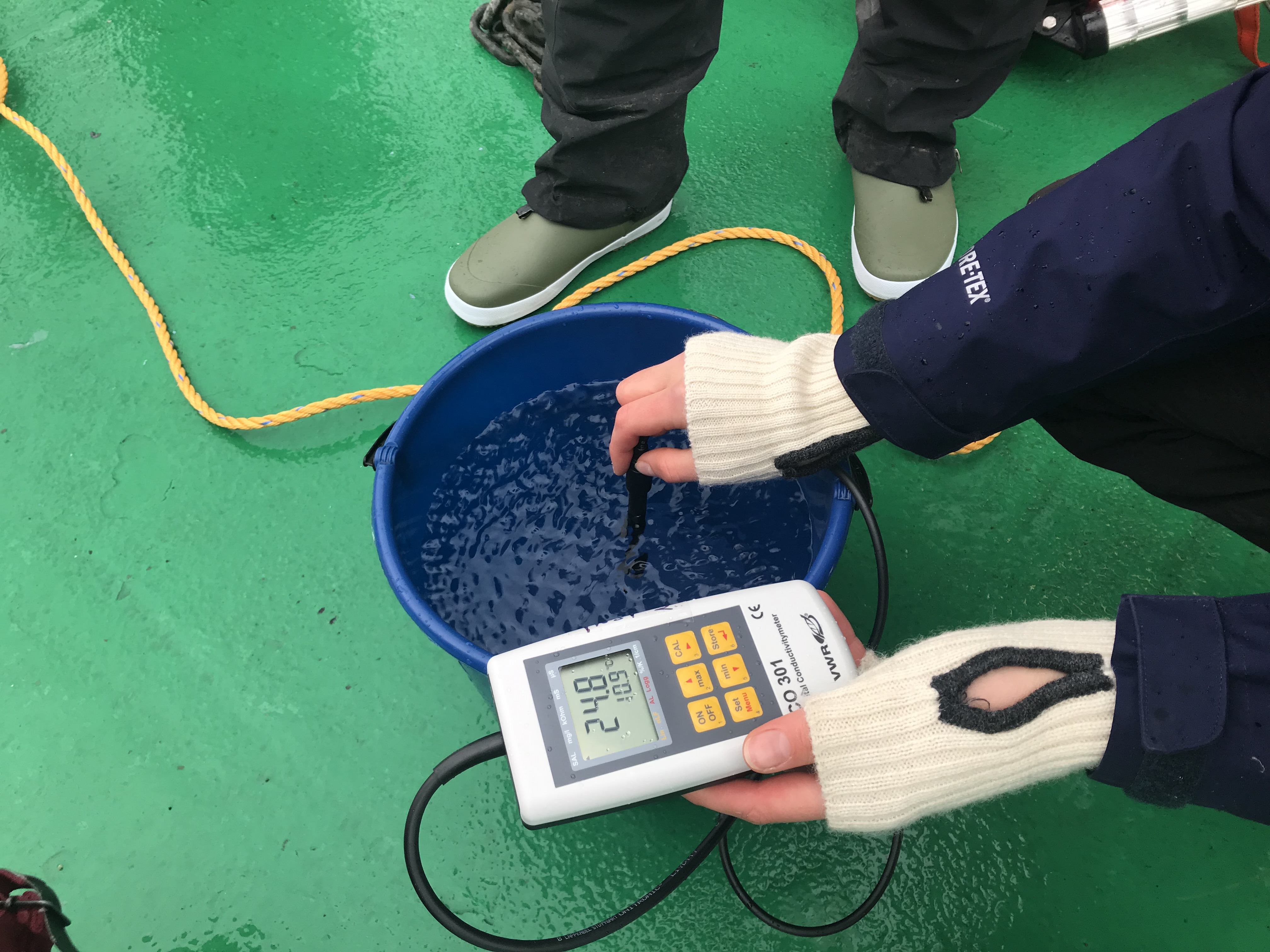
Wave watching in a bucket

On the GEOF105 student cruise that I was lucky enough to join like I did last year, I happened to observe what you see in the picture above: Standing waves in a bucket! And this isn’t a staged photo, this is me taking a picture of a student at work.

We are looking at the bucket the students use to take surface water samples which they measure on deck. The bucket happens to stand just above the engine room. Which leads to vibrations. Which, in turn, leads to waves. Many different kinds of waves! In addition to what you see above, we find, for example, plain circular waves. They might look like they do in the picture below:

And here is a short movie of the waves, first in real time, then in slow motion.

Sometimes the circular waves also have other wave lengths.

The next pattern that develops from a monopole (like the one you see above) is my favourite: A monopole with higher order stuff developing at the edge of the bucket.

Watch the movie below to see it in motion (first at real speed, then in slow motion).

The next step, then, is water that almost looks as if it was boiling. Like so:

Here is a movie of the bucket with the “boiling” wave pattern, again in real time first and then in slow motion.

The movie below shows a close-up of some of the waves in the “boiling” state, when there was enough energy in the system to throw drops up in the air. The movie goes from real time to slow motion. Careful when you play it, I left the sound in in order to show how the frequency of the waves is the same as the frequency of the engine. (And because of the annoying sound, it doesn’t start up automatically, so you have to click to play)

Here is a movie that shows the bucket in different positions, shot continuously to show how quickly the wave pattern develop and also how close together the different spots with the different pattern are located. Thanks for playing along, Kjersti!

So clearly the location has an influence on what wave pattern develops. But what are other important factors? We tested material, shape and size of the container.

A small plastic bucket which is almost cylindrical, for example. Guess what happens?

We can get the same wave pattern as in the large bucket! The movie below shows three different wave pattern. When the frequency suddenly changes that’s because the movie is in parts played in slow motion.

As to material: It seems to be important that it’s flexible. Iron cast pans don’t work (yes, there is water in it!), neither do metal lunch boxes…

And round shapes make nicer waves. But the rectangular vanes of the surface drifters (aka paint roller trays) also make pretty pattern! But now the waves are, unsurprisingly, only parallel to the edges of the tray.

Yep, this is the kind of stuff that makes me really happy! :-)

How to use home-made surface drifters to teach oceanography

Very early knowledge about oceanography stems from beach finds that had to have been transported to that beach from far away because the finds themselves (pieces of trees, or coconuts, or whatever) were not native to their finding places so the ocean must have provided a connection between their place of origin and the beach they ended up on. And in early oceanographic research, messages in bottles or even wood pieces marked with identifying numbers were deployed at known times and regions and then recovered wherever they made landfall to get a better idea of ocean currents. And as oceanography got more and more sophisticated as a discipline, such lagrangian (i.e. current-following) data has become an important part of oceanographic research, especially over the last two decades with profiling ARGO floats.

Position of 3930 ARGO floats that were active in the 30 days before January 18th, 2019. Source: http://www.argo.ucsd.edu

ARGO data is available to anyone and, via its Google Earth interface, easily accessible in teaching. But of course this is only a passive resource, you cannot deploy drifters wherever you would like for teaching purposes. Now imagine if you had cheap drifters* available for use in teaching, how cool would that be?

Last year I was involved in discussing the design of home-made surface drifters and later got the chance to join the student cruise (as part of Lars Henrik and Harald‘s GEOF105 class at the University of Bergen, Norway) where the drifters were tested, both in their functions as drifters and as a teaching tool. They are an amazing addition to the student cruise and a great learning opportunity! But there are also a lot of challenges that arise when with working with drifters — or opportunities to think about interesting problems! What more could an instructor (or a student!) want? :-)

Building home-made surface drifters

While in our case the drifters were developed and built before the class started, discussing design criteria with students would be a really interesting task in an applied oceanography course. The design we ended up working with with is described here.

Building those relatively cheap drifters provided us with the opportunity to have students handle them to learn to use oceanographic instrumentation without them, or us, being too concerned about the welfare of the instrumentation. It also provided us with a fleet of four drifters that we could deploy and recover on four day-long student cruises and have them right in the vicinity of where we were taking Eulerian measurements at the same time, so we would end up with a complementing data set and could discuss the benefits of each of the two kinds of measurements and how, when they come together, they tell a much more interesting story than any of them could on their own.

Where to deploy the drifters

If you have a limited number of drifters available (four in our case), you have to think long and hard about where to deploy them. Of course you can just dump them into the water anywhere and see where they end up. But in order to figure out the best spot, it is really helpful to have a clear idea of what influences the currents in the regions you are interested in, and what path the drifters might take, depending on the location of their deployment.

On the three first days of the student cruise, we saw the drifters move against the predicted tidal current (“predicted” tidal currents, because we didn’t look at direct observations of the tidal current, so we don’t actually know if it is behaving the way the prediction predicted) and, at times, also against the main wind field. Nevertheless, we expect the wind to have a large influence on the flow in the surface layer, hence the day at sea starts with a briefing on the weather forecast.

Students presenting the weather forecast for the cruise day in the ship's messe

Students presenting the weather forecast for the cruise day in the ship’s messe

In addition to thinking about a deployment strategy for specific weather conditions, it is helpful to think about how trajectories from different days will be compared to each other. Therefore we chose to deploy on two sections over four days, thus repeating each section twice.

How to track your drifters

There are many ways to track drifters. In the early days, acoustic signals were used to know where drifters moved within an array of sound sources. These days, most tracking is done using GPS. In our case, we used readily available GPS tracking units that were then mounted on the drifters (see below).

GPS units being fixed to the drifters onboard RV Hans Brattstrøm

GPS units being fixed to the drifters onboard RV Hans Brattstrøm

Looking at the features of the GPS units we used, they were apparently mainly designed to tracking cars when you’ve lend them to your kids. In any case you can set alarms if velocities are too high, if they leave a pre-defined area, etc.. Interesting to see what kind of products are on the market!

Looking at how to track the drifter, i.e. the specifications of the GPS sender, might also be a very interesting exercises to do with students. How often should it “call home”, what battery lives are needed, how will the data be transferred, where and how can it be accessed, stored, processed?

How to deploy your drifters

Even when you know where to deploy the drifters, that doesn’t tell you how to deploy them. And even from a small research ship like the Hans Brattstrøm it is not immediately obvious how to do it.

Deploying a drifter

Very good reality check on how difficult it is to get instrumentation in place to measure oceanographic data!

How to interpret your data

Speaking of oceanographic data — how do you actually interpret it? Below you see a snapshot of our four drifters in action. This is actually on of the more interesting times when it comes to velocities: We do have two drifters moving with 4km/h and then one with less than 3km/h (which shows up as not moving because of some algorithm in the website). But what does this actually tell us?

Position and approximate velocities of our four drifters at the end of day 4

Interpreting drifter data becomes very difficult very quickly when you are in a flow field that changes over time. We did have the tidal forecast and the wind forecast, but both only in a coarse resolution in space and time and so it gets really difficult to imagine how they might have influenced the currents and thus the trajectories of the drifters!

How to protect your drifters from damage

Even in a fjord that is sheltered from the wind and big waves of the open ocean, the sea is still a harsh environment and large forces will act on the drifters. If we want to be able to recover the drifters in one piece, we have to make sure that they are actually sturdy enough to stay in one piece.

One of our drifters capsized for unknown reasons. Luckily Algot was still able to recover it!

Another point to consider is how much buoyancy a drifter will need to stay afloat, yet to be submerged enough into the water to actually follow the surface current rather than being pushed through the water by winds, or pushed over by the winds as the one above.

How to find your drifters again

As we think about how to protect the drifter from damage, we also need to think about how we can make sure the drifter stays upright so the GPS antenna stays above the water level. Even with fairly good visibility and low waves, and despite the brightly colored flags and radar reflectors on the drifters, they were pretty difficult to spot!

Even though we can see the drifter’s position through an app on my phone, it is really difficult to spot it out on the water!

How to recover your drifters

Even on a small vessel like the one we used for the student cruise, the water is actually pretty far away from where you can stand on the deck, so recovering a bulky and heavy item out of the sea is not as straight forward as one might think!

Technician Algot and a student recovering one of the surface drifters

Making sense of your drifters’ trajectories

This is not something I can cover in this post, of course — it’s what Inga will do for her Master’s thesis. Below, you see her plotting trajectories from the four days together with the predicted wind fields of the respective days.

, and think about how we can make sure the drifter stays upright so the GPS antenna stays above the water level.

Inga looking at analyses of the drifters’ trajectories which she will explain in her Master’s thesis

But there are several aspects I find especially interesting for discussions with students:

  • At which depth range did we place the anchor of the drifter, i.e. what “surface current” are we actually tracking, the real surface, or an average over the top 0.5 meters, or the top 1 meter? And what would “average” even mean? Or something else?
  • When we have Eulerian data from, say, tidal gauges, weather stations, etc, how do we bring those together with the Lagrangian data provided by the drifters?
  • Knowing what we know now, what could we learn for future deployment strategies?

There are so many super interesting questions to be discussed using this fairly inexpensive instrumentation that it is a great opportunity that should not be missed!

*of course, ARGO uses profiling floats that actively measure data and send them home, whereas we use surface drifters that only send their position and nothing else. But maybe we can mount data loggers on them next time? :-)

Need your help! “Wish list” for a student lab for tank experiments?

I’d love your input: If your student lab for GFD tank experiments had to downsize, but you had to present a “wish list” for a smaller replacement, what would be on that list? Below are my considerations, but I would be super grateful for any additional input or comments! :-)

Background and “boundary conditions”

The awesome towing tank that you have come to love (see picture above) will have to be removed to make room for a new cantina. It might get moved into a smaller room, or possibly replaced all together. Here are some external requirements, as far as I am aware of them:

  • the (new) tank should ideally be movable so the (small) room can be used multi-purpose
  • since the new room is fairly small, people would be happy if the new tank was also smaller than the old one
  • the rotating table is kept (and a second, smaller one, exists in the building)
  • There are other, smaller tanks that will be kept for other experiments, dimensions approximately 175x15x40cm and smaller
  • the whole proposal needs to be inexpensive enough so that the likelyhood that it will actually be approved is moderate to fair ;-)

Here are a couple of things I think need to be definitely considered.

Dimensions of the tank

If the tank was to be replaced by a smaller one, how small could the smaller one be?

The dimension of the new tank depend, of course, on the type of experiment that should be done in the tank. Experiments that I have run in the tank that is to be replaced and that in my opinion should definitely be made possible in the new location/tank include

  1. “Dead water”, where a ship creates internal waves on a density interface (instructions)
  2. Internal lee waves & hydraulic jumps, where a mountain is moved at the bottom of the tank (instructions)
  3. Surface imprints of internal waves (example)
  4. Surface waves (example)
  5. Intrusions (example)
  6. Waves in a density stratification (example)
  7. Surface waves running up on a slope (I haven’t blogged about that yet, movies waiting to be edited)

If we want to be able to continue running these experiments, here is why we should not sacrifice the dimensions of the tank.

Why we need the tank length

The first reason for keeping the length of the tank is that the “mountains” being towed to create the lee waves are already 1 and 1.5m long, respectively. This is a length that is “lost” for actual experiments, because obviously the mountain needs space inside the tank on either end (so in its start and end position). Additionally, when the mountain starts to move, it has to move for some distance before the flow starts displaying the features we want to present: Initially, there is no reservoir on the “upstream” side of the mountain and it only builds up over the first half meter or so.

The second reason for keeping the length of the tank are wave reflections once the ship or mountain comes close to the other side of the tank. Reflected surface waves running against the ship will set up additional drag that we don’t want when we are focussing on the interaction between the ship and the internal wave field. Reflected internal waves similarly mess things up in both experiments

The third reason for keeping the length of the tank is its purpose: as teaching tank. Even if one might get away with a slightly shorter tank for experiments when you just film and investigate the short stretch in the middle of the tank where there are no issues with either the push you gave the system when starting the experiment or the reflections when you get near the end, the whole purpose of the tank is to have students observe. This means that there needs to be a good amount of time where the phenomenon in question is actually present and observable, which, for the tank, means that it has to be as long as possible.

Why we need the tank width

In the experiments mentioned above, with exception of the “dead water” experiment, the tank represents a “slice” of the ocean. We are not interested in changes across the width of the tank, and therefore it does not need to be very wide. However, if there is water moving inside the tank, there will be friction with the side walls and the thinner the tank, the more important the influence of that friction will become. If you look for example at the surface imprint of internal wave experiment, you do see that the flow is slowed down on either side. So if you want flow that is outside of the boundary layers on either side, you need to keep some width.

Secondly, not changing the tank’s width has the advantage that no new mountains/ships need to be built.

Another, practical argument for a wide-ish tank (that I feel VERY strongly about) is that the tank will need to be cleaned. Not just rinsed with water, but scrubbed with a sponge. And I have had my hands inside enough tanks to appreciate if the tank is wide enough that my arm does not have to touch both sides at all times when reaching in to clean the tank.

Why we need the tank depth

The first reason for keeping the height is that for the “dead water” experiment, even the existing tank is a lot shallower than what we’d like from theory (more here). If we go shallower, at some point the interactions between the internal waves and the ground will become so large that it will mess up everything.

Another reason for keeping the depth is the “waves running up a slope” experiment. If you want waves running up a slope (and building up in height as they do), you have the choice between high walls of the tank or water spilling. Just sayin’…

And last not least: this tank has been used in “actual” research (rather than just teaching demonstrations, more on that on Elin’s blog), so if nothing else, those guys will have thought long and hard about what they need before building the tank…

Historical images of research on internal lee waves being done with the tank

Without getting too philosophical here about models and what they can and cannot achieve (and tank experiments being models of phenomena in the ocean), the problem is that scaling of the ocean into a tiny tank does not work, so “just use a mountain/boat half the size of the existing ones!” is actually not possible. Similarly to how if you build the most amazing model train landscape, at some point you will decide that tiny white dots are accurate enough representations of daisies on a lawn, if you go to a certain size, the tank will not be able to display everything you want to see. So going smaller and smaller and smaller just does not work. A more in-depth and scientific discussion of the issue here.

Other features of the tank

When building a new tank or setting up the existing tank in a new spot, there are some features that I consider to be important:

  • The tank needs a white, intransparent back wall (either permanently or draped with something) so that students can easily focus on what is going on inside the tank. Tank experiments are difficult to observe and even more difficult to take pictures of, the better the contrast against a calm background, the better
  • The tank should be made of glass or some other material that can get scrubbed without scratching the surface. Even if there is only tap water in the tank, it’s incredible how dirty tanks get and how hard they have to be scrubbed to get clean again!
  • The tank needs plenty of inlets for source waters to allow for many different uses. With the current tank, I have mainly used an inlet through the bottom to set up stratifications, because it allowed for careful layering “from below”. But sometimes it would be very convenient to have inlets from the side close to the bottom, too. And yes, a hose could also be lowered into the tank to have water flow in near the bottom, but then there needs to be some type of construction on which a hose can be mounted so it stays in one place and does not move.
  • There needs to be scaffolding above the tank, and it needs to be easily modifiable to mount cameras, pulleys, lights, …
  • We need mechanism to tow mountains and ships. The current tank has two different mechanisms set up, one for mountains, one for ships. While the one for the ship is home-made and easily reproducible in a different setting (instructions), the one to tow the mountain with is not. If there was a new mechanism built, one would need to make sure the speeds at which the mountain can be towed matches the internal wave speed to be used in the experiment, which depends on the stratification. This is easy enough to calculate, but it needs to be done before anything is built. And the mechanism does require very securely installed pulleys at the bottom of the tank which need to be considered and planned for right from the start.

“Source” reservoirs

The “source” reservoirs (plural!) are the reservoirs in which water is prepared before the tank is filled. It is crucial that water can be prepared in advance; mixing water inside the tank is not feasible.

There should be two source reservoirs, each large enough to carry half the volume of the tank. This way, good stratifications can be set up easily (see here for how that works. Of course it works also with smaller reservoirs in which you prepare water in batches as you see below. But what can happen then is that you don’t get the water properties exactly right and you end up seeing stuff you did not want to see, as for example here, which can mess up your whole experiment)

Both reservoirs should sit above the height of the tank so that the water can be driven into the tank by gravity (yes, pumps could work, too, more on that below).

“Sink” reservoir

Depending on the kind of dyes and tracer used in the water, the water will need to be collected and disposed of rather than just being poured down the drain. The reservoir that catches the “waste” water needs to

  • be able to hold the whole volume of the tank
  • sit lower than the tank so gravity will empty the tank into the reservoir (or there needs to be a fast pump to empty the tank, more on that below)
  • be able to be either transported out of the room and the building (which means that doors have to be wide enough, no steps on the way out, …) or there needs to be a way to empty out the reservoir, too
  • be able to either easily be replaced by an empty one, or there needs to be some kind of mechanism for who empties it within a couple of hours of it being filled, so that the next experiment can be run and emptied out

If the waste water is just plain clear tap water, it can be reused for future experiments. In this case, it can be stored and there need to be…

Pumps

If reservoirs cannot be located above and below tank height to use gravity to fill and empty the tanks, we need pumps (plural).

  • A fast pump to empty out the tank into the sink reservoir, which can also be used to recycle the water from the sink reservoir into the source reservoirs
  • One pump that can be regulated very precisely even at low flow rates to set the inflow into the tank
  • Ideally, a second pump that can be regulated very precisely, so the double bucket method of setting up a stratification in a tank can be done automated rather than relying on gravity.

Preferable the first and the latter are not the same, because changing settings between calibrating the pump for an experiment, setting it on full power to empty the tank, and calibrating it again will cause a lot of extra work.

Inlets for dyes

Sometimes it would be extremely convenient if there was a possibility to insert dyes into the tank for short, distinct periods of time during filling to mark different layers. For this, it would be great to be able to connect syringes to the inlet

Hoses and adapters

I’ve worked for years with whatever hoses I could find, and tons of different adapters to connect the hoses to my reservoir, the tap, the tank. It would be so much less of a hassle if someone thought through which hoses will actually be needed, bought them at the right diameter and length, and outfitted them with the adapters they needed to work.

Space to run the experiment

The tank needs to be accessible from the back side so the experimenter can run the experiment without walking in front of the observers (since the whole purpose of the tank is to be observed by students). The experimenter also needs to be able to get out from behind the tank without a hassle so he or she can point out features of interest on the other side.

Also, very importantly, the experimenter needs to be able to reach taps very quickly (without squeezing through a tight gap or climbing over something) in case hoses come loose, or the emergency stop for any mechanism pulling mountains in case something goes wrong there.

Space for observers

There needs to be enough room to have a class of 25ish students plus ideally a handful of other interested people in the room. But not only do they need to fit into the room, they also need to be able to see the experiments (they should not have to stand in several rows behind each other, so all the small people in the back get to see are the shoulders of the people in front). Ideally, there will be space so they can duck down to have their eyes at the same height as the features of interest (e.g. the density interface). If the students don’t have the chance to observe, there is no point of running an experiment in the first place.

Filming

Ideally, when designing the layout of the room, it is considered how tank experiments will be documented, i.e. most likely filmed, and there needs to be space at a sufficient distance from the tank to set up a tripod etc..

Lighting

Both for direct observations and for students observing tank experiments, it is crucial that the lighting in the room has been carefully planned so there are minimal reflections on the walls of the tank and students are not blinded by light coming through the back of the tank if a backlighting solution is chosen.

Summary

In my experience, even though many instructors are extremely interested in having their students observe experiments, there are not many people willing to run tank experiments of the scale we are talking about here in their teaching. This is because there is a lot of work involved in setting up those experiments, running them, and cleaning up afterwards. Also there are a lot of fears of experiments “going wrong” and instructors then having to react to unexpected observations. Running tank experiments requires considerable skill and experience. So if we want people using the new room and new tank at all, this has to be made as easy as possible for them. Therefore I would highly recommend that someone with expertise in setting up and running experiments, and using them in teaching, gets involved in designing and setting up the new room. And I’d definitely be willing to be that person. Just sayin’ ;-)

Why are they so much slower than I thought? Observing the group velocity vs phase velocity of waves

Have you ever seen a speedboat drive past, looked at its wake moving torwards you, then gotten distracted, and when you look back a little while later been surprised that the wake hasn’t moved as far towards you as you thought it would have during the time you looked away?

Well, I definitely have had that happen many times, and the other day I was sitting on the beach with a friend and we talked about why you initially perceive the waves moving a lot faster than they turn out to be moving in the end. While I didn’t film it then, I’ve been putting my time on the GEOF105 student cruise to good use to check out waves in addition to the cool research going on on the cruise, so now I have a movie showing a similar situation!

But let’s talk a little theory first.

Phase velocity

The phase velocity of a wave is the speed with which you see a wave crest moving.

Waves can be classified into long vs short waves, or deep- vs shallow water waves. But neither deep and shallow, nor long and short are absolute values: They refer to how long a wave is relative to the depth of the water in which it is moving. For short or deep water waves, the wavelength is short relative to the water depth (but can still be tens or even hundreds of meters long if the water is sufficiently deep!). For long or shallow water waves, the wave length is long compared to the water depth (for example Tsunamis are shallow water waves, even though the ocean is on average about 4 km deep).

For those long waves, or shallow water waves, the phase velocity is a function of the water depth, meaning that all shallow water waves all move at the same velocity.

However, what you typically see are deep water waves, and here things are a little more complicated. Since phase velocity depends on wave length, it is different for different waves. That means that there is interference between waves, even when they are travelling in the same direction. So what you end up seeing is the result of many different waves all mixed together.

If you watch the gif below (and if it isn’t moving just give it a little moment to fully load, it should then start), do you see how waves seem to be moving quite fast past the RV Harald Brattstrøm, but once you focus on individual wave crests, they seem to get lost, and the whole field moves more slowly than you initially thought?

That’s the effect caused by the interference of all those waves with slightly different wave lengths, and it’s called the group velocity.

Group velocity

The group velocity is the slower velocity with which you see a wave field propagate. It’s 1/2 of the phase velocity, and it is the velocity with which the signal of a wave field actually propagates. So even though you initially observed wave crests moving across the gif above fairly quickly, the signal of “wave field coming through!” only propagates with half the phase velocity.

Usually you learn about phase and group velocities in a theoretical way and are maybe shown some animations, but I thought it was pretty cool to be able to observe it “in situ!” :-)

At the end of the rainbow you’ll find … home-made surface drifters

For Lars Henrik and Harald‘s GEOF105 class we are deploying home-made surface drifters on the student cruise. Today I had the opportunity to join the cruise again, and since the weather today made for beautiful pictures, I just have to share them here.

First, at the end of every rainbow, as we all know, you’ll find … home-made surface drifters!

Inga and Algot getting the drifters ready for deployment

Inga and Algot getting the drifters ready for deployment

The research ship we are on is the Hans Brattstrøm — cosy ship with a super nice and helpful crew!

We are sailing on RV Hans Brattstrøm

We are sailing on RV Hans Brattstrøm

The drifters themselves are equipped with a sea anchor made from a plastic bucket and four paint roller trays underneath a buoy, and then on top all kinds of equipment to make sure nobody runs over it: A safety flag, a lamp, a radar reflector. And, of course, the GPS sender!

Isn't it cool how those wave rings radiate from our drifter?

Isn’t it cool how those wave rings radiate from our drifter?

What we are using those surface drifters for? To determine the circulation in the fjord right outside Bergen. There are several things that might have an influence: Tides, wind, freshwater runoff from the land… And a tilted sea surface (although it is probably not as tilted as in the picture below…)

Drifter in front of RV Hans Brattstrøm in front of mountains covered in clouds

Drifter in front of RV Hans Brattstrøm in front of mountains covered in clouds

Another amazing day “at sea”, thanks for having me along, Lars Henrik!

Drifter in front of RV Hans Brattstrøm

Drifter in front of RV Hans Brattstrøm

Taking water samples

A big part of any oceanographic research cruise: Taking water samples.

Here is a group of students practicing how to arm Niskin bottles that will go into the ocean open on both ends, and that will then, when the whole rosette is on its way up again, be closed one after another at depths that promise to be interesting in terms of water properties.

Arming those Niskin bottles is actually not as easy as it looks, there is a strong spring going through the bottle, connecting the lids. And it is actually pretty painful if you accidentally close the bottles while some part of your body is between the bottle and the lid. Ask me how I know…

When the bottles are all open, the rosette can be lifted off the deck and into the sea.

Usually, rosettes are equipped with instrumentation in addition to the Niskin bottles, usually a CTD, measuring conductivity (to calculate the salinity from), temperature, and depth (actually measuring pressure, which converts easily into depth). I contributed to a very nice movie about how CTDs work a couple of years ago, check it out!

And now the rosette is finally in the water.

Water samples in physical oceanography are mainly used to calibrate the sensors on the CTD, which give (pretty much) continuous measurements throughout the whole depth of the water column. And that’s also what we want to use our water samples for — we have a hand-held conductivity probe that is right now producing values that cannot be correct. How we are going to deal with that? We (and you!) will find out tomorrow! :-)

Home-made surface drifters

A bicycle safety flag, a plastic bucket, four paint roller trays — what are those people doing there?! Until now this might almost count as kitchen oceanography!

Home-made surface drifters

But it’s only almost kitchen oceanography; at least my kitchen isn’t usually stocked with GPS trackers, which is what is mounted on this contraption. Let alone the research ship we used to deploy it. So this must surely count as real oceanography then!

Lars Henrik and students deploying a surface drifter to measure the surface current in a fjord

Lars Henrik and students deploying a surface drifter to measure the surface current in a fjord

Above, you see  Lars Henrik and his students deploying a surface drifter. The red buoy keeps it floating at the surface, the chain hanging below is heavy enough to make sure it stays upright. The bucket and four paint roller trays act as sea anchor so the whole thing moves with the water rather than being blown about by the wind. A safety flag, radar reflector and light make sure nobody accidentally sails over it, and the GPS sender lets the position be tracked.

For example like this:

Screen shot of the map and the drifter positions from my mobile phone

Screen shot of the map and the drifter positions from my mobile phone

Above, you see what it looked like when we had already deployed three of our four surface drifters (the red ones that are moving so slowly that the software tells us they aren’t moving at all), while the fourth one is still onboard the ship, moving to the position where it will be deployed (the green one moving at 3km/h).

Follow their positions on your mobile device!

Following surface drifters’ paths in real time is pretty awesome in itself, but what makes it even better is that the GPS positions can be accessed online from any device. Below, for example, you see the positions on my phone with the drifters behind it in the water (if you look really closely, that is. But they were there!).

My mobile phone with the drifters' positions and the drifters in the background

My mobile phone with the drifters’ positions and the drifters in the background

What you also see is that three of the drifters have huddled together after a couple of hours out in the fjord. Nobody really knows why yet, but that’s what we are here to find out!

Just from observing the wind and the movement of the drifters throughout the day, it seemed that the surface circulation in this fjord is dominated by the wind over the tides. But there will be a Master’s thesis written on the data we collected today (plus a lot more data and a regional ocean model!) so we’ll soon know how good my assumptions are and what really drives the surface currents here.

Three of the drifters huddling together due to currents that have yet to be understood

Three of the drifters huddling together due to currents that have yet to be understood

Come time to recover the drifters, the weather wasn’t quite as nice as earlier throughout the day. Just to give you an impression of the conditions under which the drifters were recovered:

Algot and Inga recovering a drifter

Algot and Inga recovering a drifter

Yep, if you look at the sea state, there is nothing to complain about, really, just a little water coming from the sky! But it was cold water… ;-)

And everything got recovered safely and made it back to port — ready to be deployed again tomorrow to gather more data and understand the fjord a little better. Exciting times! Thanks for letting me be part of this GEOF105 adventure, Lars Henrik!

The drifters coming home to the port of Bergen

The drifters coming home to the port of Bergen