Tag Archives: rotation

Combining rotation of a water tank with a temperature gradient: A Hadley cell circulation demo!

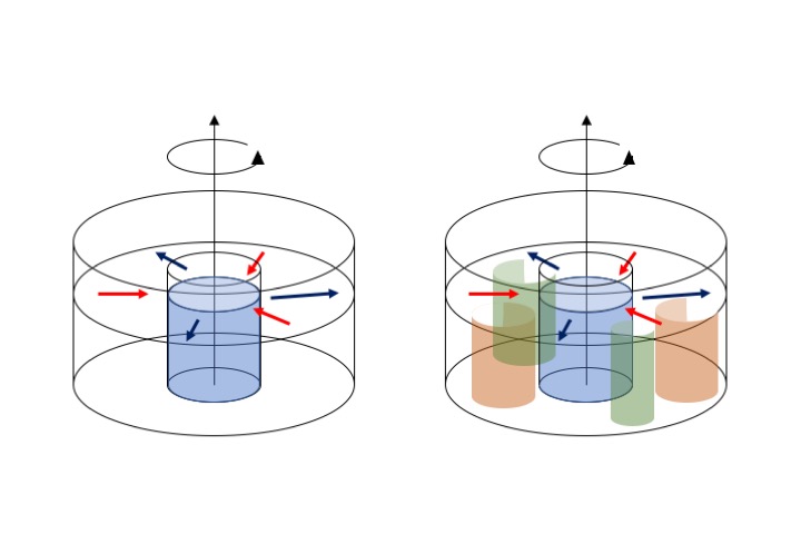
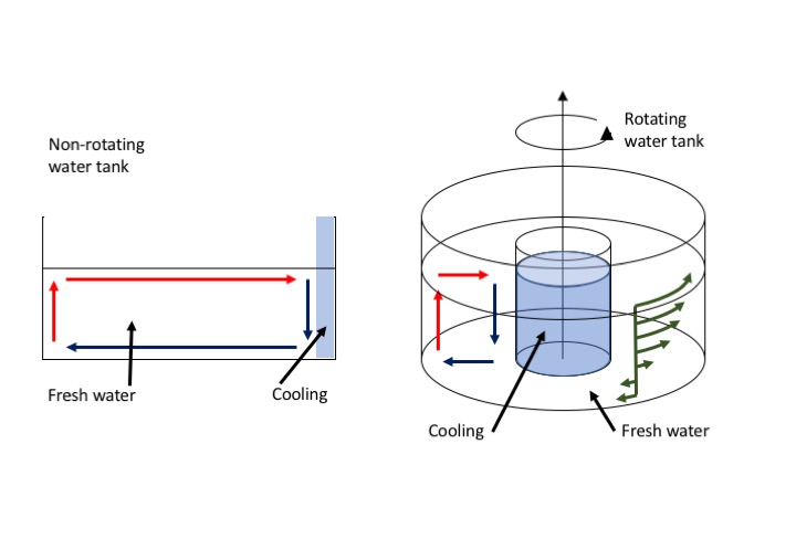
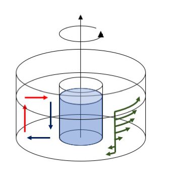
Yesterday, we combined a thermally-driven overturning circulation with the effects of rotation, and thus created a Hadley cell circulation. And while the tank was turning faster than we would have liked, we still managed to create a circulation that largely resembles the sketch below: An axially-symmetric overturning circulation (with cold water, indicated by blue arrows, moving down near the cooling in the middle and then outwards, and warmer water moving up along the outer rim and then towards the middle of the tank) which induces the thermal wind flow (sketched in green: Fast surface current in the direction of rotation but even faster than the tank is rotating, and slow bottom flow in the opposite direction).

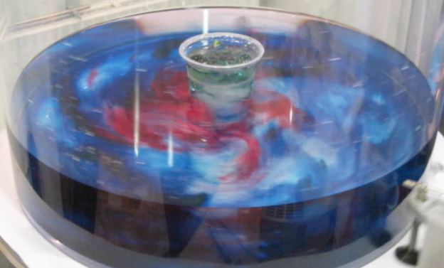
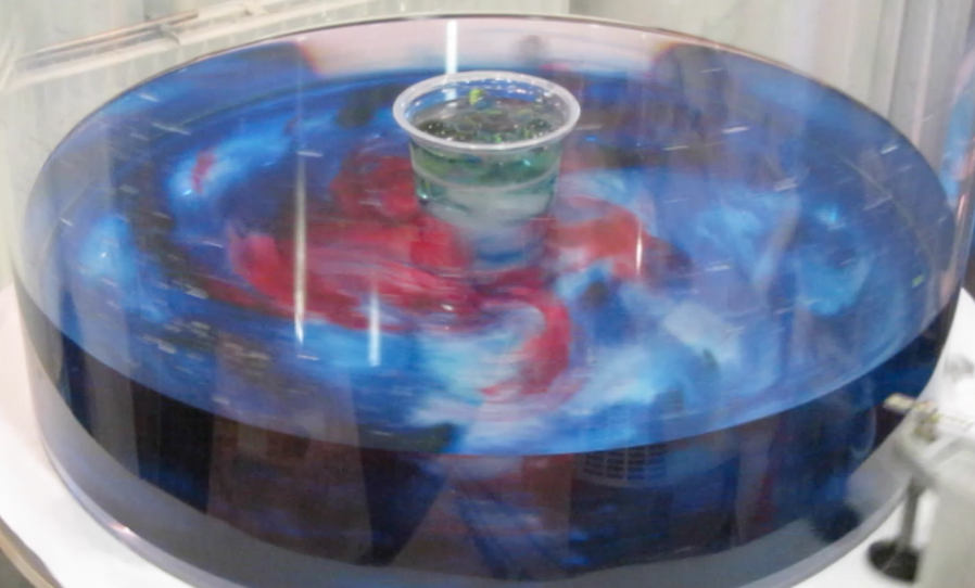
But what would happen if we increased the tank’s rotation rate? It would make the induced azimuthal flow, the thermal wind, faster too, until it eventually becomes unstable and breaks down into eddies. And then, the experiment (first blogged about a long time ago) looks similar to this one: Lots and lots of eddies that are now rigid vertically and move as Taylor columns!

Heat exchange between the cold core and the warmer areas towards the rim of the tank now doesn’t happen via overturning any more, but looks something like sketched below: We now have radial currents bringing warm water towards the middle (red) and cold water away from it (blue), and the eddies that create those currents are coherent over the whole depth of the tank.

This is actually a really nice demonstration of the circulation in mid- and high latitudes where the weather is determined by baroclinic instabilities, i.e. weather systems just like the eddies we are showing here.

Btw, having two different experiments both represent the same Hadley cell circulation isn’t a contradiction in itself: On Earth, the Coriolis parameter changes with latitude, but in the tank, the Coriolis parameter is the same throughout the tank. So depending on what latitude we want to represent, we need to change the tank’s rotation rate.

Here is an (old) movie of the experiment, and I can’t wait for our own tanks to be ready to produce a new one!


Combining a slowly rotating water tank with a temperature gradient: A thermal wind demonstration!

Setting up an overturning circulation in a tank is easy, and also interpreting the observations is fairly straightforward. Just by introducing cooling on one side of a rectangular tank a circulation is induced (at least for a short while until the tank fills up with a cold pool of water; see left plot of the image below).

But now imagine an axially symmetric setup where the cooling happens in the middle. What will happen to that overturning circulation if the tank is set into rotation (see right plot above)?

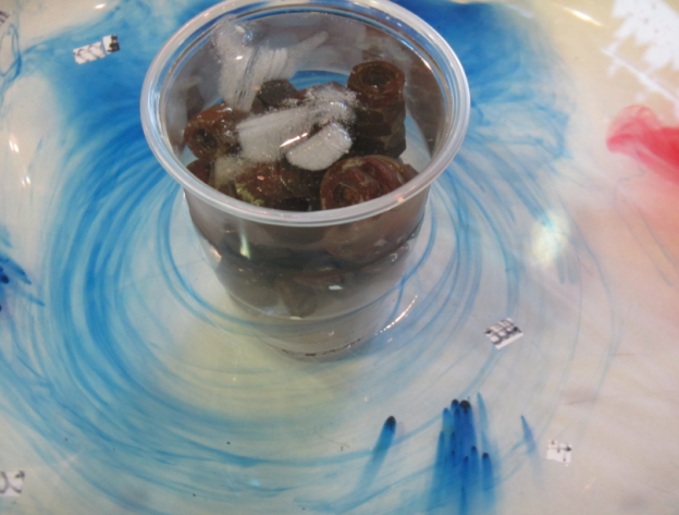
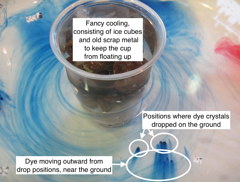
First, let’s check there is an overturning circulation. We can see that there is when we look at dye crystals that sank to the bottom of the tank: Dye streaks are moving outwards (and anti-clockwise) from where the crystals dropped on the ground, so at least that part of the overturning circulation is there for sure. If our tank were taken to represent the Hadley cell circulation in the atmosphere, this bottom flow would be the Trade winds.

Now, in addition to having water sink in the middle of the tank, spread radially outwards, and returning by rising near the outer edge of the tank and flowing back towards the middle, a secondary circulation is induced, and that’s the “thermal wind”. The thermal wind, introduced by the temperature gradient from cold water on the inside of the tank to warmer waters towards the rim, tilts columns that would otherwise stay vertically.

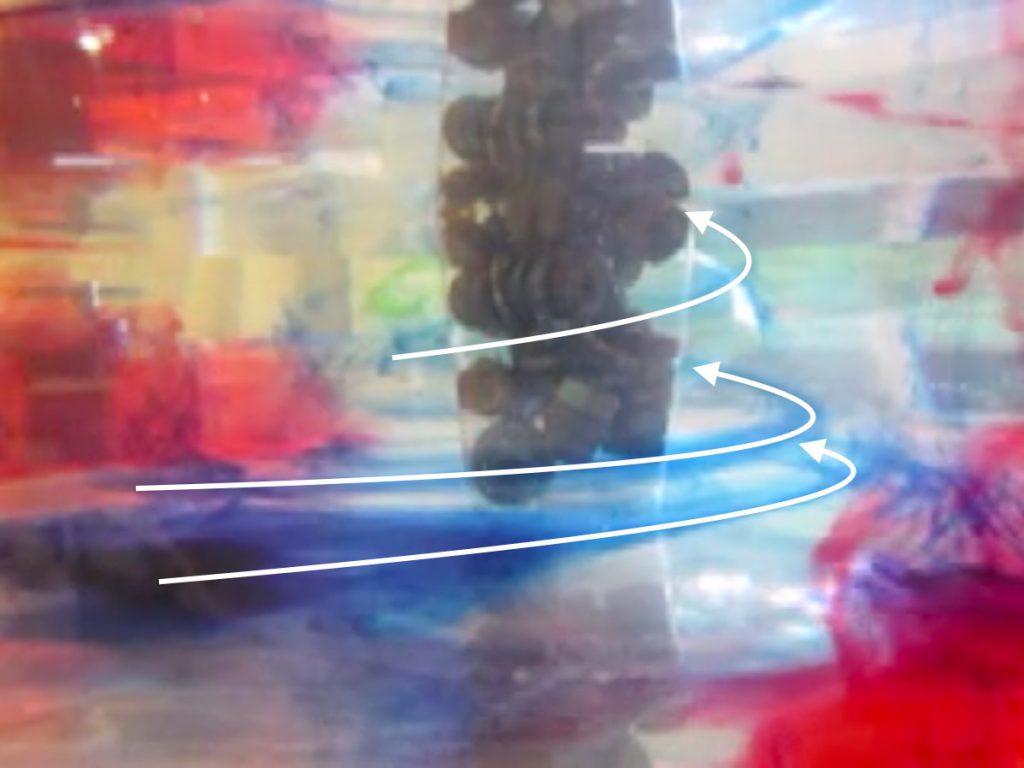
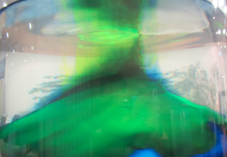
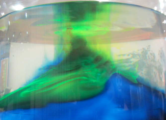
You see that in the image below: Dye dropped into the tank does not sink vertically, but gets swirled around the cold center in a helix shape, indicated in the picture below by the white arrows. In that picture, the swirls are tilted very strongly (a lot stronger than we’d ideally have them tilted). The reason for that is that we just couldn’t rotate the tank as slowly as it should have been, and the higher the rotation rate, the larger the tilt. Oh well…

So this is the current pattern that we observe: An overturning circulation (sketched with the red arrows representing warmer water and the blue arrows representing colder waters below), as well as the thermal wind circulation (indicated in green) with stronger currents near the surface (where the water is moving in the same direction as the rotating tank, but even faster!) and then a backward flow near the bottom. The velocities indicated here by the green arrows are what ultimately tilted our dye streaks in the image above.

The thermal wind component arises because as the overturning circulation moves water, that water carries with it its angular momentum, which is conserved. So water being brought from the rim of the tank towards the middle near the surface HAS to move faster than the tank itself the closer it gets to the middle. This flow would be the subtropical jets in the Hadley cell circulation if out tank were to represent the atmosphere.

Here is an old video of the experiment, first shown 5 years ago here. I’m looking forward to when Torge’s & my rotating tanks are ready so we can produce new videos and pictures, and hopefully being able to rotate the tank even more slowly than we do here (but that was the slowest possible rotation with the setup we had at that time). I promise you’ll see them here almost in realtime, so stay tuned! :-)

Why do we need a rotating tank to study ocean and atmosphere dynamics? A demonstration

For our project “Ocean currents in a tank: From dry theory to juicy reality“, Torge, Joke and I are working on building affordable rotating tanks to use in Torge’s Bachelor class on ocean and atmosphere dynamics. When people ask what we need rotating tanks for, the standard answer is that rotation of the tank simulates rotation of the Earth. Which is of course true, but it is not really satisfying because it doesn’t really convey the profound effect that rotation has on the behaviour of the ocean and atmosphere, which is actually very easy to show in a quite dramatic way (at least I think it’s dramatic ;-)).

Imagine a cylindrical tank filled with fresh water. In its middle, we place a (bottom-less) cylinder filled with dyed, salty water. When we lift the cylinder out of the tank, the blue dye is released into the freshwater. And depending on whether the tank is rotating or not, the blue water behaves very differently.

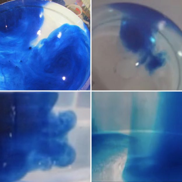
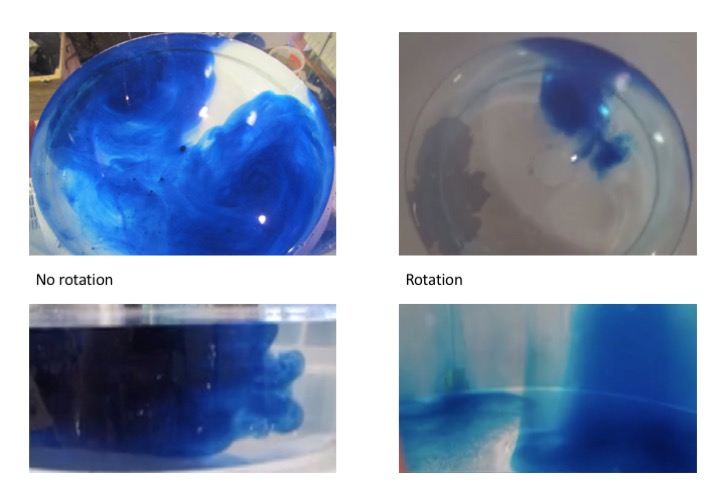
The picture below shows top views and side views of a non-rotating and a rotating experiment, taken after similar amounts of time after the “release” of the blue water.

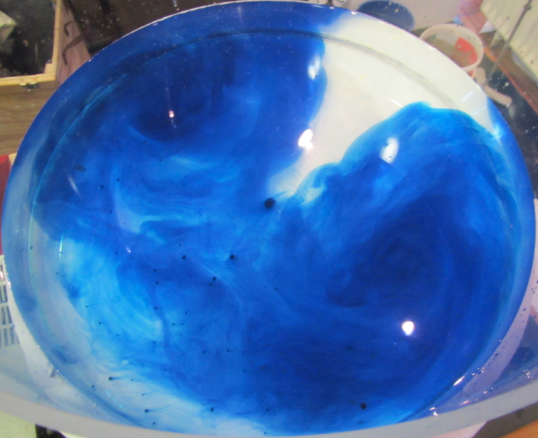
Let’s focus on the top view first. In the non-rotating experiment, a dipole of two counter-rotating eddies develops within seconds of the central dense column being released, spreading blue water pretty much all throughout the tank. In the rotating experiment, after a similar amount of time, the dipole looks different: Even though the same amount of dyed water was released, the two eddies are much smaller and much more well-defined.

In the side view, the difference becomes even more clear. In the non-rotating experiment, looking at the boundary between the blue and clear water, we see eddies moving water in all directions, so in combination with the top view, we know that turbulence is three-dimensional.

In the rotating experiment, however, the boundary between blue and clear water looks very different. There is a clear separation between a blue column of water and the clear water surrounding it. From the side view, we don’t see any turbulence. We know, however, from the top view that there is turbulence in the horizontal plane. In the rotating case, turbulence is two-dimensional.

And this is the dramatic difference between rotating and non-rotating fluids: rotating fluids are rigid in a way that non-rotating fluids are not. And this means that they behave in fundamentally different ways: rather than developing in 3 dimensions, they only develop in 2 dimensions. So in order to simulate the atmosphere and ocean of the rotating earth correctly, we need to also rotate our water tank.

P.S.: Images for this post were originally posted in this post (and in other posts linked therein) 5 years ago. Hoping we’ll have new images soon when our new tanks are up and running! :-)

Demonstrating Ekman layers in a rotating tank: High pressure and low pressure systems!

Ekman spirals — current profiles that rotate their direction over depth, caused by friction and Coriolis force — are really neat to observe in a rotating tank. I just found out that they are apparently (according to Wikipedia) called “corkscrew currents” in German, and that’s what they look like, too. I tend to think of Ekman spirals more as an interesting by-product that we observe when stopping the tank after a successful experiment, but they totally deserve to be featured in their own experiments*.

Ekman layers form whenever fluid is moving relative to a boundary in a rotating system. In a rotating tank, that is easiest achieved by moving the boundary relative to the water, i.e. by increasing or decreasing the rotation rate of a tank and observing what happens before the water has adjusted to the new rotation and has reached solid body rotation. Spinning the tank up or down creates high and low pressure systems, respectively, similar to atmospheric weather system.

Creating a low-pressure system: Slowing down the tank

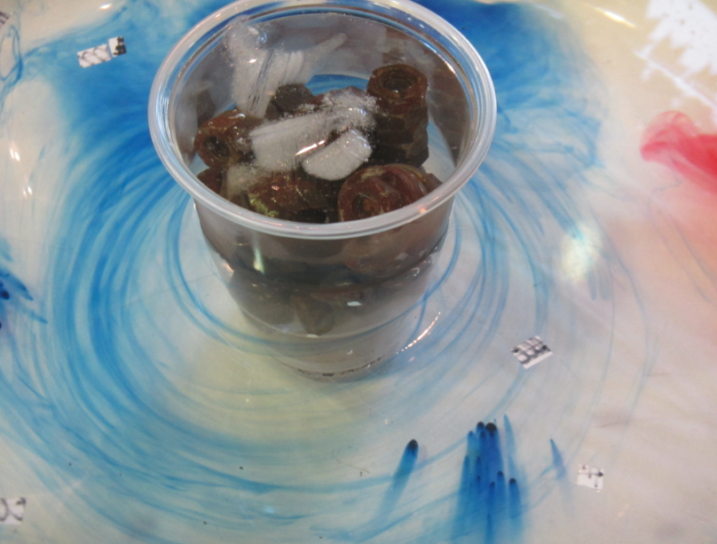
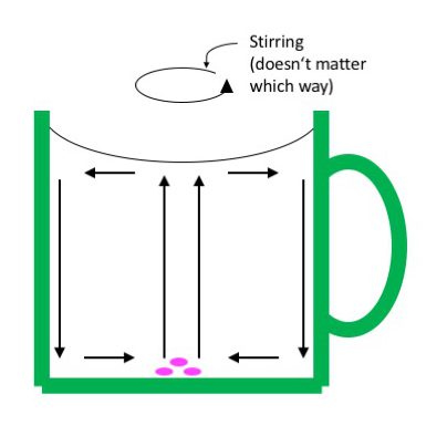
In atmospheric low pressure systems, air moves towards the center of the low pressure system, where it rises, creating the low pressure right there. This situation can probably easiest be modelled by stirring a cup of tea that has some tea leaves still in it. As the surface deforms and water bunches up at the sides, an overturning circulation is set into motion. Water sinks along the side walls and flows towards the center of the cup near the bottom. From there it rises, but any tea leaves or other stuff floating around get stuck in the middle on the bottom because they are too heavy to rise with the current. So there you have your low pressure system!
You can observe the same thing with a rotating tank, except now we don’t stir. The tank is filled with water and spun up to solid body rotation on the rotating table. When the water is in solid body rotation, a few dye crystals are dropped in, leaving vertical streaks as they are sinking to the ground (left plot in the image below).

Then the tank is slowed down. The resulting friction between the water body and the tank creates a bottom Ekman spiral. The streaks of dye that were left when the dye crystals were dropped into the tank move with the water when the tank is slowed down. In the upper part of the tank, the dye stripes stay vertical. But at the bottom, within the Ekman layer, they get deformed as the bottom layer lifts up, and thus show us the depth over which the water column is influenced by bottom friction (see black double arrow in the right plot in the picture below). Again, we have created a low pressure system with a similar overturning circulation as we saw in the tea cup.
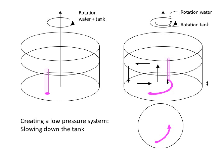
In the bottom right corner of the image above, we see a top view of the tank with the trajectory the dye is taking from the spot where it rested on the ground before the rotation of the tank changed.

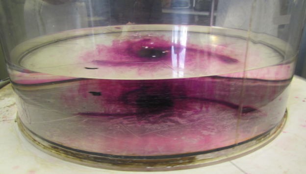
Looking into the tank with a co-rotating camera, we can also observe the Ekman depth, i.e. the depth that is influenced by the bottom: We see a clear distinction between the region where the dye streaks from the falling crystals are still vertical and the bottom Ekman layer, where they are distorted, showing evidence of the friction with the bottom.

So this was what happens when water is spinning relativ to a slower tank (or a non-rotating cup) — the paraboloid surface is adjusting to one that is more even or completely flat. But then there is also the opposite case.

Creating a high-pressure system: Spinning up the tank

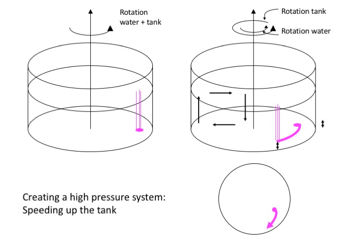
If we take water that is at rest and start spinning the tank (or spin a moving tank faster suddenly), we create a high pressure system until we again reach solid body rotation.

Again, we dropped dye crystals when the water was in solid body rotation (or in solid body without rotation) before we start the spinup, as we see in the left plot below.

Now the sudden spinning of the boundaries relative to the body of water creates a high pressure system with the bottom flow outward from the center, which again we see in the deformation of the dye streaks. The Ekman depth is again the depth over which the dye streaks get bent, below the water column that isn’t influenced by friction where they still have their original vertical shape.

In the bottom right corner of the image above, we see a top view of the tank with the trajectory the dye is taking from the spot where it rested on the ground before the rotation of the tank changed.

Here is what this experiment looks like in a movie:

So here we have it. High pressure and low pressure systems in a tank!

*Which I actually did before, both in a rotating tank as well as on a Lazy Susan.
Why do we go to all the hassle of rotating our swimming pool?

This blog post was written for Elin Darelius & team’s blog (link) which you should totally follow if you aren’t already!

We have started rotating and  filling water into our 13-meter-diameter rotating tank! So exciting! Pictures of that to come very soon.

But first things first: Why do we go to the trouble of rotating the swimming pool?

The Earth’s rotation is the reason why movement that should just go straight forward (as we learned in physics class) sometimes seems to be deflected to the side. For example, trade winds should be going directly towards the equator from both north and south, since they are driven by hot air rising at the equator, which they are replacing. Yet we see that they blow towards the west in addition to equatorward. And that is because the Earth is rotating: So even though the air itself is only moving towards the equator, when observed from the Earth, the winds seem to be deflected by what is called the Coriolis force.

The influence of the Coriolis force becomes visible when you look at weather systems, which also swirl, rather than air flowing straight to the center where it then raises. Or when you look at tidal waves that propagate along a coastline rather than just spreading out in all directions. Or when you look at ocean currents. But all of these effects are fairly large-scale and not so easy to observe directly by just looking up in the sky or out on the ocean for a short while.

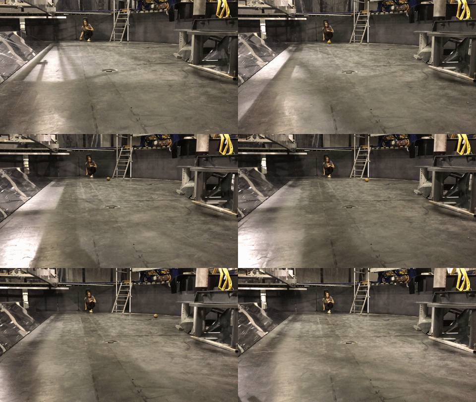
There are however easy ways to experience the Coriolis force when you play on a merry-go-round or with a record player or with anything rotating, really. Those are obviously spinning much faster than the Earth, and that’s exactly the point: The faster rotation makes it easy for us to see that something is going on. And obviously, Nadine and I had to test just that on the best merry-go-round that I have ever seen:

And that is what we’ll use in our experiments, too: Since our topography is a lot smaller than the real world it is representing, we also have to turn the tank faster than the real world is turning in order to get comparable flow fields. How to exactly calculate how fast we need to turn we’ll talk about soon. Stay tuned! :-)

Nadine demonstrating the -- southern hemisphere! -- Coriolis defliection

Nadine demonstrating the — southern hemisphere! — Coriolis defliection

The effects of rotation on a collapsing column

Comparing a rotating and non-rotating dipole.

I just realized that I never explicitly showed the difference between rotation and no rotation, even though I do have the footage to do so: Two experiments set up to create a monopole, which both turned dipole.

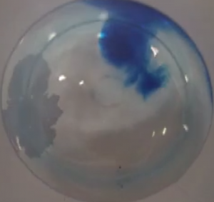
In the non-rotating experiment (which was, by the way, set up carefully in preparation for a rotating experiment, but then the v-belt on the rotation table failed [but luckily this was on the last night of the JuniorAkademie, so we had otherwise run everything we had been planning to run], so we ended up with a non-rotating experiment), the dipole shown below develops within seconds of the central dense column being released.

IMG_9100

A dipole created by releasing a column of dense water in the middle of a non-rotating tank.

In the rotating experiment, however, this is what the dipole looks like after a similar amount of time:

And we see that in the non-rotating case, the eddies are spreading to fill the whole width of the tank within seconds, whereas in the rotating case the eddies mainly stay confined into their respective columns. This is the often quoted phenomenon of conservation of vorticity in a rotating system, where movements happen mostly in the horizontal plane, whereas in non-rotating system, vertical movements happen easily, too (i.e. the dense water from the upper part of the initial dense column can sink to the bottom of the tank in this case, which it could not do in the rotating case), and turbulence can hence develop in 3D and not only 2D.

For videos of both experiments, please check out the posts on the rotating case and the non-rotating case.

Simulations of hetonic explosions

Because sometimes it’s easier to control a computer than rotation, salinity, water and dye.

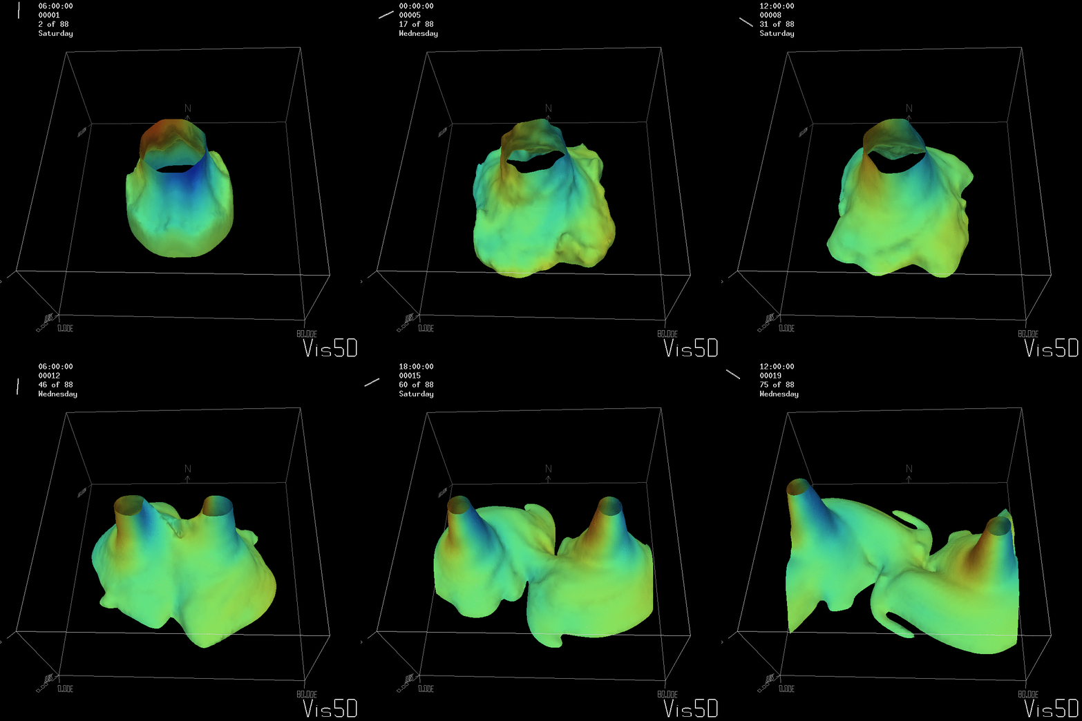
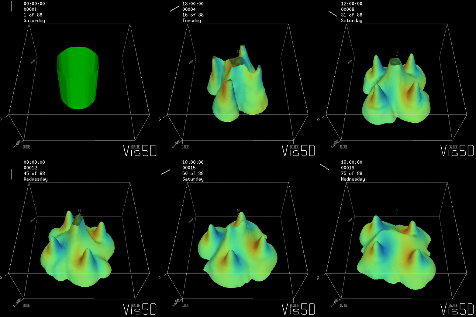
After looking at a non-rotating cylinder collapse the other day, it is time to look at proper hetonic explosions (you know? The experiment on the rotating tank where a denser column of water at the center of the tank is released when the whole tank has reached solid body rotation). In Bergen, we used to show this experiment as a “collapsing column” experiment, the tilting of a frontal surface under rotation. For those cases, all the parameters of the experiment, e.g. the rotation rate, the density contrast, the water height, the width of the cylinder, were set up such as to ensure that one single column would persist in the middle of the tank. At JuniorAkademie, we’ve also run it in other setups, to form dipoles or quadrupoles. For a real hetonic explosion, we would typically go for even more eddies than that.

Screen shot 2014-08-25 at 7.36.25 PM

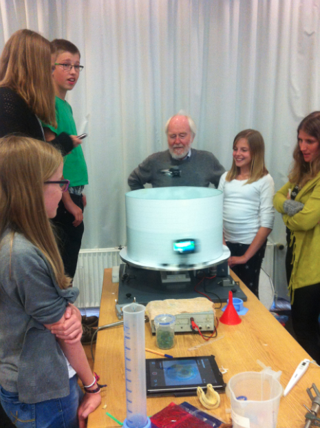
Students watching the experiment shown below. We put paper on the outside of the tank because all the feet swiping past are kind of distracting on the movie later, but that is obviously really annoying for live observers. But in our defense – we only did this once for one experiment late one evening, and didn’t expect so many people to be interested in the experiment! Plus they got to watch on the tablet which showed the top-camera’s view via WiFi… ;-)

But if you read through all those posts then, you might remember that I’ve been complaining about how it is really difficult to set up an experiment in such a way that you have total control over the amount of vortices that form. Firstly, because the system is inherently chaotic, but let’s forget about that for a minute. But then because the calculations aren’t that easy for school kids to do, and then even when everything is calculated correctly, water has to be prepared with the correct salinity, the rotation has to be set to the correct period, the cylinder has to be completely centered in the tank, the water level has to be just right and when the cylinder is pulled up, this has to happen with a swift movement as to add as little disturbance as possible. Not an easy task, especially when there is a camera mounted on the tank!

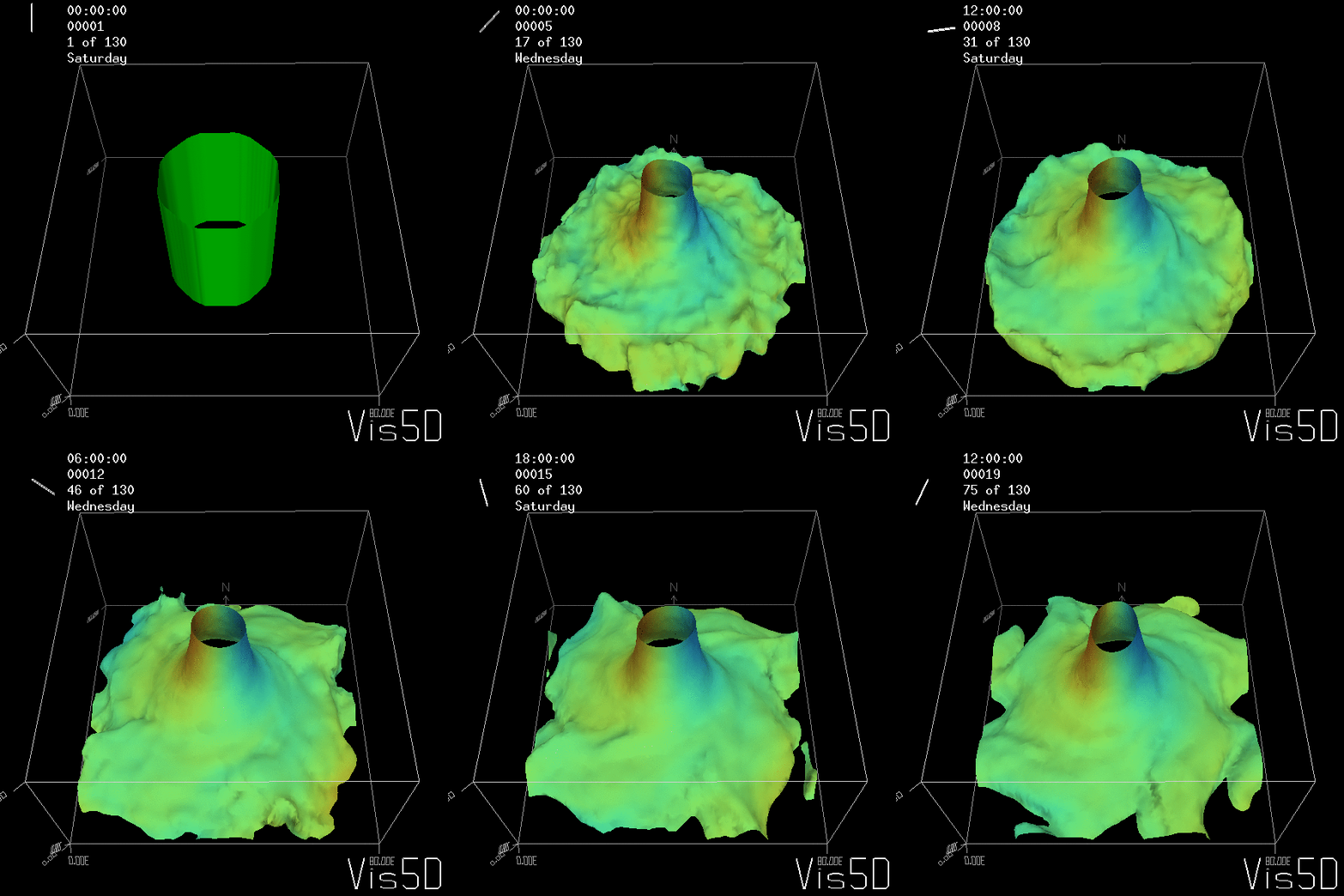
To show us what to expect, Rolf did some model simulations for us. This is what a monopole looks like:

Shown is an isoline in density, separating the dense water below from the lighter water above. Superimposed are the horizontal velocities, so you get a sense of the rotation.

For more advanced experimentalists to recreate, here a dipole:

As for the monopole, you see chimneys that are open on top. That is because the density is higher than the one of the isoline inside the eddy, so you get the impression that you can look inside.

But the picture is different for quadrupoles, here the four eddies (that form when the central column breaks up) do not reach the water surface any more, hence they appear closed in the visualization below.

Btw, the time is of course not measured in weekdays, that’s just a glitch in the visualization that we didn’t fix.

Seeing the simulated situations for the three cases above was quite comforting  after having run this experiment a couple of times. When you run the experiment in a tank, there is always a lot of turbulence that you wish wasn’t there. But it really helps to keep your expectations in check when you see that in the simulation there are always little vortices, trying to break away from the main ones, too, and that that is how it is supposed to be.

So now for an attempted experimental monopole, which turned out as a dipole due to turbulence introduced when removing the cylinder, similarly to what happened to us in the no-rotation collapsing column experiment.

When you watch the side views closely, you can see that the tank appears to be wobbling (which we usually can’t see, because this is the only time we taped a camera to the side of a tank – usually when filming from the side, I film from outside the rotating system, holding the camera in my hand). You see it most clearly when the yellow dye crystals are added – the water is sloshing back and forth, and that is most definitely not how it is supposed to be. Oh, the joys of experimentation! But what is pretty awesome to see there is how the vertical dye streaks get pulled apart into sheets as they get sucked into the vortices. Reminds me of Northern Lights! :-)

Cylinder collapse on a cone

Water running uphill during spin-down – how much more awesome can it get?

After hours, when all but the most curious students had left, Rolf and I ran another collapsing cylinder experiment, this time on Rolf’s old disk player turned rotating table.

IMG_9097

Rolf setting up the experiment

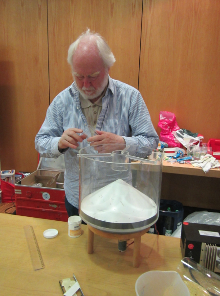
Rolf has a cone-inset for the round tank, and we set a cylinder on top of the cone and filled it with dyed salt water. The rest of the tank was filled with fresh water and the whole system spun up into solid body rotation. Then the cylinder was pulled out and here is what happened:

IMG_9107

Column sitting on top of the cone!

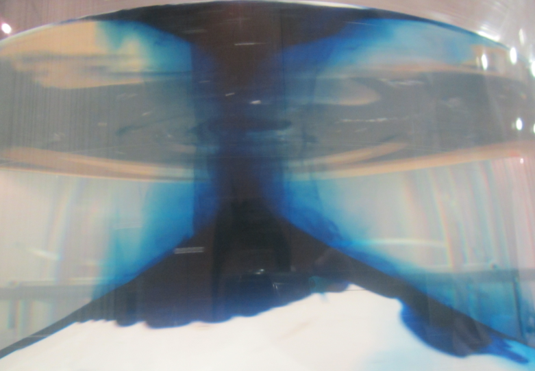
The column sat right on top of the cone! And stayed there, and stayed there, and stayed there. Slowly a bottom boundary layer started creeping down the slope, so we decided to add more color.

IMG_9119

Still only one column on top of the cone

Nice to see that, for a change, we calculated all the parameters correctly! But then The Boss himself had done the calculations this time round…

IMG_9120

The column creeping back up the slope during spin-down

But the most fascinating thing happened during spin-down when we had stopped the tank: The column slowly withdrew up the slope again! Our two fascinated students were absolutely wowed (and that’s saying something – they were really impressed with the salt fingers earlier already).

Watch the movie below for some impressions of the experiment.

Hetonic explosion

Trying to tweak conditions to force a set number of vortices.

We’ve done the hetonic explosion again. This time the group was super careful to calculate the Rossby radius correctly, and then to set up the experiment accordingly. We aimed for a single column like in our tilting of a frontal surface under rotation experiment.

We did manage to create one main vortex, but we saw at least two additional smaller vortices. And since we know how vortices are created, it is pretty likely that there were four in total.

But never mind, it is still a very nice experiment that we are happy to do over and over again!

Movies will come up once I have time to actually write the posts – we do have numerical simulations that we want to compare our experiments with. Stay tuned!

Hadley cell circulation – slow rotation

In order to not be in the eddying regime, this time we are rotating our tank as slowly as possible.

Since we ran the Hadley cell experiment the other day, I’ve been obsessed with running it again, this time with the slowest rotation possible in order to visualize a different flow regime – one were the heat transport happens through an overturning circulation rather than through eddies.

Unfortunately the camera we had mounted above the tank only started up halfway through the experiment (no idea how that happened!), so today you’ll only get snippets of this experiment. But all the more reason for us to run it again soon!

And I promise you’ll get a discussion of the differences between this and the Hadley cell experiment with the higher rotation rate soon. I just don’t have the time or mental space to write more than a couple of incoherent sentences while I’m still at the JuniorAkademie