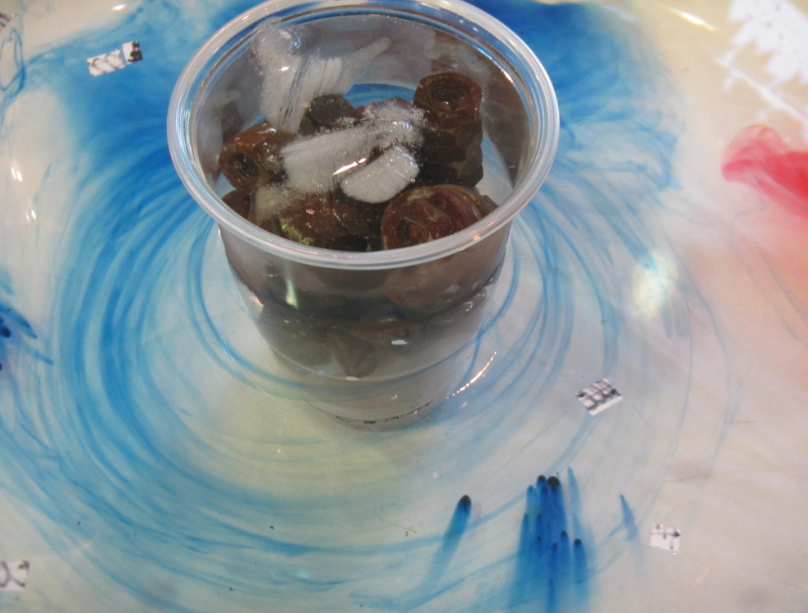
Combining a slowly rotating water tank with a temperature gradient: A thermal wind demonstration!
Setting up an overturning circulation in a tank is easy, and also interpreting the observations is fairly straightforward. Just by introducing cooling on one side of a rectangular tank a circulation is induced (at least for a short while until the tank fills up with a cold pool of water; see left plot of the image below).
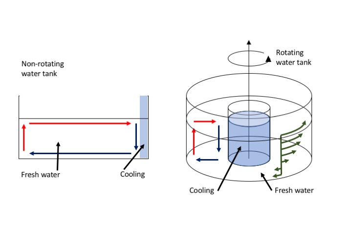
But now imagine an axially symmetric setup where the cooling happens in the middle. What will happen to that overturning circulation if the tank is set into rotation (see right plot above)?
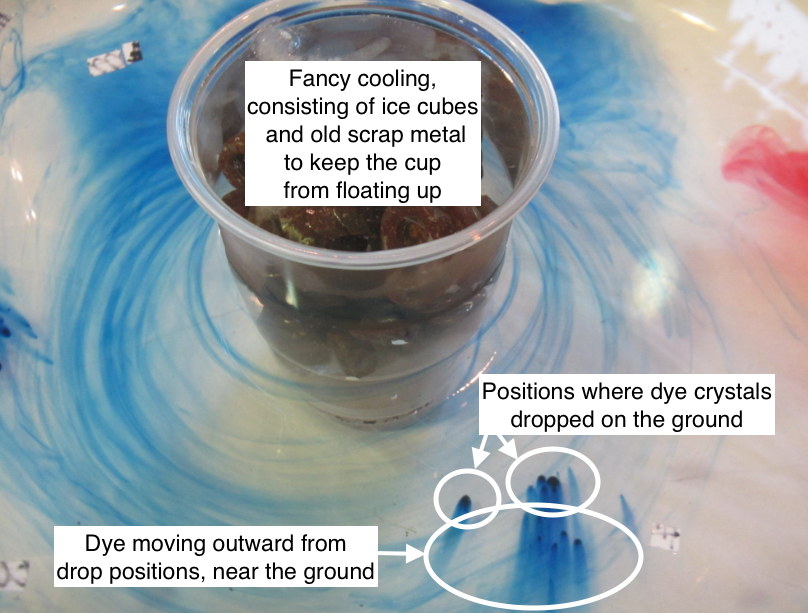
First, let’s check there is an overturning circulation. We can see that there is when we look at dye crystals that sank to the bottom of the tank: Dye streaks are moving outwards (and anti-clockwise) from where the crystals dropped on the ground, so at least that part of the overturning circulation is there for sure. If our tank were taken to represent the Hadley cell circulation in the atmosphere, this bottom flow would be the Trade winds.
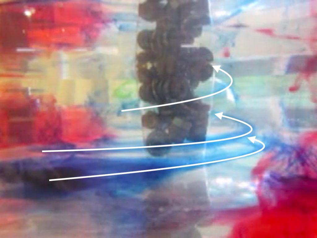
Now, in addition to having water sink in the middle of the tank, spread radially outwards, and returning by rising near the outer edge of the tank and flowing back towards the middle, a secondary circulation is induced, and that’s the “thermal wind”. The thermal wind, introduced by the temperature gradient from cold water on the inside of the tank to warmer waters towards the rim, tilts columns that would otherwise stay vertically.
You see that in the image below: Dye dropped into the tank does not sink vertically, but gets swirled around the cold center in a helix shape, indicated in the picture below by the white arrows. In that picture, the swirls are tilted very strongly (a lot stronger than we’d ideally have them tilted). The reason for that is that we just couldn’t rotate the tank as slowly as it should have been, and the higher the rotation rate, the larger the tilt. Oh well…
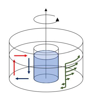
So this is the current pattern that we observe: An overturning circulation (sketched with the red arrows representing warmer water and the blue arrows representing colder waters below), as well as the thermal wind circulation (indicated in green) with stronger currents near the surface (where the water is moving in the same direction as the rotating tank, but even faster!) and then a backward flow near the bottom. The velocities indicated here by the green arrows are what ultimately tilted our dye streaks in the image above.
The thermal wind component arises because as the overturning circulation moves water, that water carries with it its angular momentum, which is conserved. So water being brought from the rim of the tank towards the middle near the surface HAS to move faster than the tank itself the closer it gets to the middle. This flow would be the subtropical jets in the Hadley cell circulation if out tank were to represent the atmosphere.
Here is an old video of the experiment, first shown 5 years ago here. I’m looking forward to when Torge’s & my rotating tanks are ready so we can produce new videos and pictures, and hopefully being able to rotate the tank even more slowly than we do here (but that was the slowest possible rotation with the setup we had at that time). I promise you’ll see them here almost in realtime, so stay tuned! :-)
Combining rotation of a water tank with a temperature gradient: A Hadley cell circulation demo! | Dr. Mirjam S. Glessmer says:
[…] we combined a thermally-driven overturning circulation with the effects of rotation, and thus created a Hadley cel…. And while the tank was turning faster than we would have liked, we still managed to create a […]