Tag Archives: tank experiment

Tides in a rotating tank

A first attempt where gravity (due to a tilted axis of rotation) replaces the pull of the moon. (deutscher Text unten)

The movie contains both a view from a co-rotating camera and from a non-rotating camera.

Gezeiten im rotierenden Tank, in dem die Anziehung durch den Mond durch Erdanziehung simuliert wird, die wir durch eine schräg stehende Rotationsachse simulieren. Im Film zeigen wir sowohl den Blick aus mit-rotierender Perspektive, als auch nicht-rotierend.


Why we absolutely need toy boats at the JuniorAkademie

Luckily I’m not the only one believing that we absolutely need remotely controlled boats! – Zum Glück bin ich nicht die Einzige, die findet, dass wir ferngesteuerte Boote brauchen!

Mein Boot hat Hochkonjunktur. D. kann es in einem Tank wenden, der nur etwa 1.5 mal so breit ist wie das Boot lang! Das kann man im Film unten bewundern. Der Film zeigt eine der ersten Wendungen, mittlerweile wendet er ohne die Ränder zu berühren. Ich hingegen komme nur um die Kurve wenn ich mit Bande spiele, und auch dann nur mit Mühe…

Und dann ist da ja noch das U-Boot. Was wir heute in Schichtung ausprobiert haben. Interne Wellen anzuregen war nicht so einfach, aber Vermischung ist doch auch was schönes!

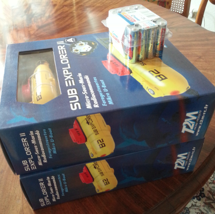
Und dann bekam ich heute morgen von meinen Eltern das Foto unten geschickt mit dem Kommentar “Eins ist für uns”. Offensichtlich haben sie erkannt, dass man wirklich ferngesteuerte U-Boote braucht! Sind meine Eltern super oder sind meine Eltern super?

Thermally-driven overturning circulation

Cooling on one end of the tank, heating on the other: A temperature-driven overturning. [deutscher Text unten]

Always one of my favorite experiments – the overturning experiment (and more, and more).

IMG_8467

Final preparations. – Letzte Vorbereitungen

Unsere “Klima und Strömungen”-Gruppe hat heute ausprobiert, wie man in einem Tank eine Umwälzströmung erzeugen kann, indem man an einem Ende wärmt und am anderen Ende kühlt. Einige Versuche waren nötig, bis das Experiment perfektioniert war: Am Anfang fehlte die Wärmequelle am einen Ende, was aber erst auffiel als das kalte Wasser am Boden schon das Ende erreicht hatte. Dann war die Wärmequelle zwar vorhanden, aber von außen am Plexiglastank angebracht.

IMG_8482

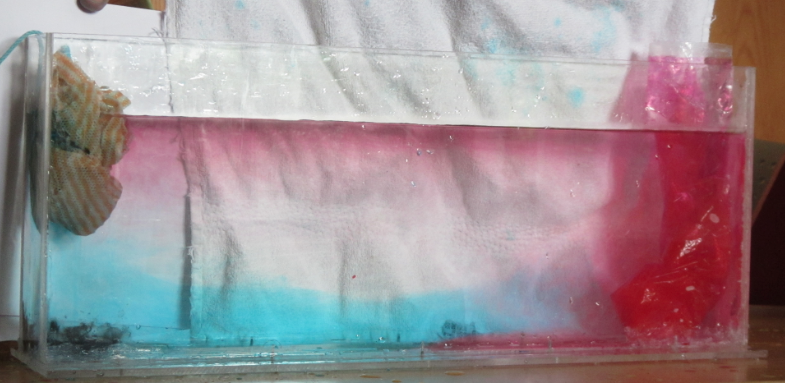
Warm red surface current, cold blue deep current. – Warme rote Oberflächenströmung, kalte blaue Tiefenströmung.

Letztendlich wurden ein rotes Wärmepack erhitzt und ein blaues Kühlpack eingefroren, und beide in den Tank gesteckt. Und voila! Eine tolle Zirkulation!

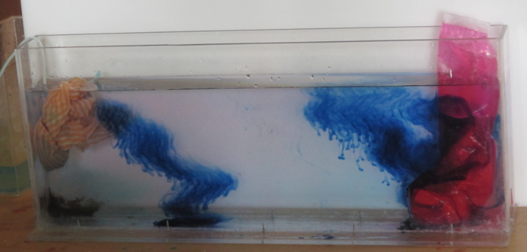
Ganz gegen Ende des Experiments haben wir dann noch Farbkristalle in den Tank fallen lassen, und wie man im Bild unten sehen kann, sind die super, um die Zirkulation zu visualisieren. Aus den anfangs senkrechten Streifen formt sich schnell ein Strömungsprofil: Am Boden von kalt nach warm (links nach rechts) und an der Oberfläche in die entgegengesetzte Richtung.

IMG_8499

Dye streaks as circulation tracers. – Blaue Farbstreifen, um die Zirkulation zu verdeutlichen.

Und wenn man ganz genau hinschaut: Salzfinger! :-)

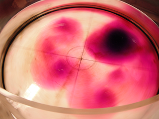
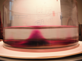
Tilting of a frontal surface under rotation

Eddy in a rotating tank.

This is an experiment that Pierre and I ran two years ago in Bergen but that – as I just realized – has not been featured on this blog before. Which is a pity, because it is a pretty cool experiment.

Under rotation, vertical fronts with different densities on either side can persist for a long time without leading to the density-driven adjustment shown in the non-rotating Marsigli experiment. This is what we demonstrate with this experiment.

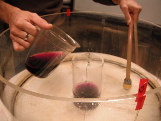
In a not-yet-rotating tank, dyed salt water is filled into a centered cylinder while, at the same time, fresh water is filled in the tank outside of the cylinder.

This setup is then spun up for approximately half an hour. Then, the cylinder can be carefully removed and the column of dense water can adjust to the new conditions.

Screen shot 2012-03-09 at 5.50.07 PM

The rotating tank just as the cylinder is being removed

When the cylinder is being removed, disturbances are being introduced. Hence, several columns with sloping fronts develop in the rotating system.

Screen shot 2012-03-09 at 5.50.16 PM

Dense columns developing towards an equilibrium state in the rotating system.

This is what the rotating tank looks like from the side several minutes after the cylinder has been removed.

Screen shot 2012-03-09 at 5.50.26 PM

Side view of the sloping front around the dense column

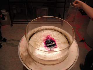
Here are a couple of movies of this experiment. First a top view (note how you can see the deformation of the surface when you focus on the reflection of the ceiling lights on the water’s surface!):

Then a side view:

And finally (just because it’s fun) this is what it looks like when you switch off the rotation of the tank when you are done with the experiment:

Modeling the Denmark Strait Overflow

Ha, this is a bad pun. We are modeling the Denmark Strait Overflow – but in a non-numerical, small-scale-and-playdough kind of way.

More than a year ago, Kjetil and I ran that experiment with a group of high-school students and when writing a post about a much more sophisticated version of this experiment I realized I never documented this one in the first place. So here we go!

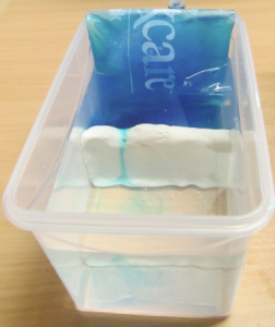
IMG_3604_small

The set-up: Tupper ware with a modeling clay ridge (“let’s call it Greenland-Scotland-Ridge”) across, filled with water to a level above the ridge, cooled with a sport’s-injury cooling pack in “the North”.

Dye is added to the “northern end” of the tank (i.e. the end where the water is being cooled by a sport’s injury cooling pack). As the water cools, it becomes denser and fills up the reservoir on the northern end until it spills over the clay ridge.

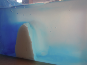
IMG_3592_small

The overflow. See the blue, dense reservoir on the left and the dense water spilling over the ridge.

This is a very simple demonstration of how overflows actually work.

IMG_3607_small

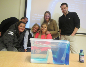
Kjetil, his Master student Eli and some of the high-school students. Can you see the sketch of the Denmark Strait Overflow on the slide in the background? (Plus, for everybody who is interested: This is the food coloring I have been using right there in the front right!)

Rogue waves in a bath tub

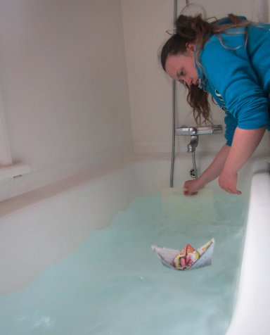
Trying to create rogue waves in the bath tub of the infamous “red house”.

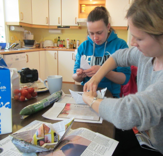
As a part of their projects, students in the CMM31 in Isafjördur course had to conduct an experiment, document and interpret it. One of the students, Silvia, chose to create rogue waves in the bath tub of the “red house”, one of the student houses, and I was invited to participate and eat delicious cupcakes.

Since rogue waves can have devastating effects on ships they encounter, clearly we had to have a ship. None were to be found, so we had to make our own.

Since most studies of rogue waves in wave tanks had a hard time actually producing the waves (and a bathtub might not be the most ideal setup) we did not have high hopes that our experiment would be successful. And we did not manage to produce rogue waves in the strict sense – but we managed to avoid major spillage of the tub and still sink a couple of the paper boats, so at least we were getting some results.

Great to see students do experiments on a Sunday afternoon!

Velocity of shallow water waves.

The experiment we run to discuss the velocity of shallow water waves.

In this post, I discussed how it took us several years to modify an experiment to make it both student and teacher-friendly. But what can you actually see in that experiment?

The movies below show the type of standing waves that are excited in the tank. This movie for 24 cm water depth (Ha – this is going to come back and haunt me! I’m not actually sure what the water depth in this experiment is. It looks like this is the case with the highest water level we have run. But if you want to know for sure go ahead, measure the period, calculate the phase velocity (the tank is 175 cm long) and then calculate the water depth. Good practice! ;-))

And then this movie shows the experiment with a lower water level (12 cm? 8? I don’t remember).

It’s interesting to see how much more difficult it is to excite a nice standing wave if you have less water in the tank. Intuitively that makes sense, but does anyone have a good, not-too-theoretical explanation?

Seesawing of standing waves.

Improving one of the experiments run in the GEOF130 lab.

One experiment that has been run in GEOF130 forever is the “standing wave”, where a wave is excited in a long and narrow tank and then, for different water depths, the period is measured and the velocity calculated in order to compare it to the one calculated from the shallow water wave equation.

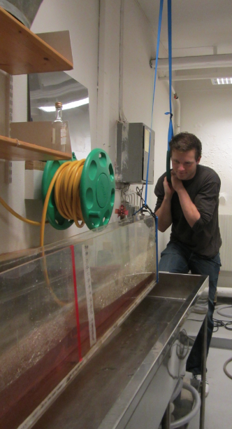
Traditionally, the standing wave is excited by lifting one end of the tank, letting the water settle down, and carefully putting the tank back down. This, however, means that someone has to lift a pretty heavy weight. So Pierre and I were quite proud of ourselves when we constructed a pulley system last year and now instead of lifting the weight up, someone could hang on a rope instead.

However, this was still hard work, and even though the picture shows a student doing the lifting, for most lab groups it was actually Pierre who did it.

But then this year, we came up with a much simpler solution and I don’t know how we didn’t see this before now. As Pierre remarked: We talk about seesawing standing waves ALL THE TIME. How did it not occur to us that the simplest setup would be a seesaw? So now we have two wooden blocks underneath the tank, one supporting it in the middle and one underneath the end where the operator is standing. So all that needs to happen now is a slight lift of the tank and then a slight downward push to bring it back in the horizontal.

So much easier!

Water seeks its level.

A solution for the siphon problem of the fjord circulation experiment.

After having run the fjord circulation experiments for several years in a row with several groups of students each year, Pierre and I finally figured out a good way to keep the water level in the tank constant. As you might remember from the sketch in the previous post or can see in the figure below, initially we used to have the tank separated in a main compartment and a reservoir.
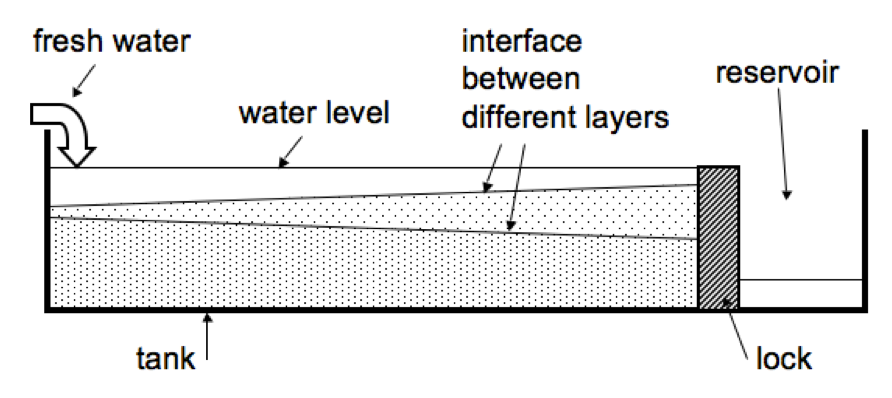
 But there were a couple of problems associated with this setup. Once, the lock separating the two parts of the tank fell over during the experiment. Then there are bound to be leaks. Sometimes we forget to empty the reservoir and the water level rises to critical levels. In short, it’s a hassle.

So the next year, we decided to run the experiment in a big sink and tip the tank slightly, so that water would just flow out at the lower end at the same rate that it was being added on the other side. Which kinda worked, but it was messy.

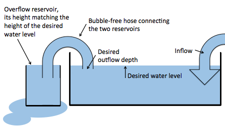
So this year, we came up with the perfect solution. The experiment is still being run in a sink, but now a hose, completely filled with water, connects the main tank with a beaker. The hight of the rim of the beaker is set to the desired water level of the big tank. Now when we add water to the big tank, there is an (almost – if the hose isn’t wide enough) instant outflow, so the water level in the tank stays the same.
Tankausfluss

New setup: A bubble-free hose connecting the tank and a reservoir to regulate the water level in the tank.

This way, we also get to regulate the depth from where the outflowing water is being removed. Neat, isn’t it?
Fjord circulation

Tank experiment on a typical circulation in a fjord.

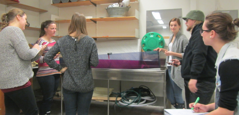
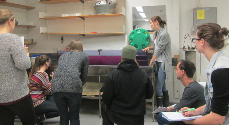
Traditionally, a fjord circulation experiment has been done in GEOF130’s student practicals. Pierre and I recently met up to test-run the experiment before it will be run in this year’s course.

This is the setup of the experiment: A long and narrow tank, filled with salt water, a freshwater source at one end and an outlet at the other end. This sets up a circulation from the head towards the mouth of the fjord close to the surface, and a deep return flow.

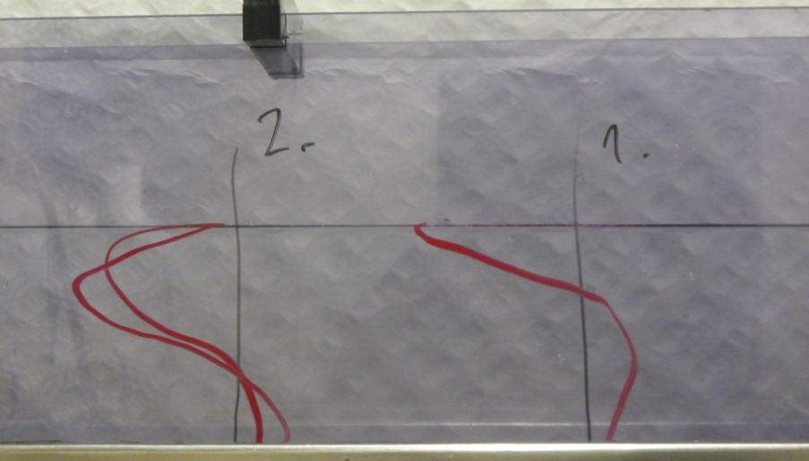
Watch the movie below to see how different circulations are set up depending on the depth of the freshwater source. As in the picture, velocity profile 1 is for the case where freshwater is being added close to the surface, and in case 2 the freshwater is being added deeper down.