Category Archives: tank experiment

Water not in solid body rotation yet

Confusing students even more by discussing how momentum is being transferred from the tank to the water.

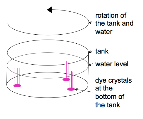
As you remember, we are preparing for the Ekman experiment and need to spin up the tank to solid body rotation.

We had started discussing how, when observed from the co-rotating camera, particles seem to be slowing down relative to the coordinate system underneath the tank as we are approaching solid body rotation.

And this is where I usually confuse the students even more, because I start talking about how momentum is being transferred from the tank to the water. For that, I point out how when observing the tank from the non-rotating framework, the particles further away from the center are moving faster than the ones closer towards the center…

(and on the screen: particles closer to the center are moving faster than the ones further away).

Why is that?

Well, for exactly the same reason we can use this setup to simulate Ekman spirals: Because when the tank is sped up or slowed down, this initially creates friction with the water inside. And as the layer that is in direct contact with the tank is brought to the same speed as the tank, it changes its velocity relative to the next layer, which creates friction and influences the movement of this second layer. And so on and so forth.

I think that it is really useful to point this out, and in some of the groups students jump at it and understand where I am going right away, but in other groups I just cannot phrase it in a way that they understand me. Or maybe they are just not as fascinated as I am by being able to see how friction inside water propagates momentum and hence don’t get excited? Who knows.

[Thanks, Pierre, for your help with the filming!]

Water in solid body rotation.

Spinning up a tank until all water particles move with the same angular velocity.

Before running the Ekman spiral experiment, the tank needs to be spun up to solid body rotation. Even though the concept itself is not difficult, it seems to be difficult to determine when a body of water has reached the point where it rotates as a solid body. So here is my attempt to sort my thoughts well enough to explain it better next time I teach this experiment.

Firstly: Solid body rotation of water in a tank basically means that every water molecule is at rest relative to the tank (neglecting thermal movement). This means that over any given period of time, particles that started out on a straight line going radially outwards from the centre will still be on straight line going radially outwards from the centre, with the same radii as initially.

But since we are usually not rotating with the tank, this is pretty hard to observe from a non-rotating frame. Enter the mounted camera rotating with the tank (and, I think, the confusion).

When we start up the rotation of the tank, the water is initially at rest in the frame of the lab. This means that for a counter-clockwise rotating table, particles on the water surface appear to be moving clockwise when observed on the screen.

As time goes by, the water inside the tank starts spinning with the tank, and with it the particles on its surface. On the screen, this appears as though the particles are slowing down.

When the particles don’t move any more relative to the coordinate system underneath the tank, the water is moving with the same speed as the tank and solid body rotation has been reached.

Part 2 will shortly be uploaded, looking into how momentum is being transferred from the tank to the water.

Ekman spiral in a tank.

Tank experiment showing (the effects of) the Ekman spiral.

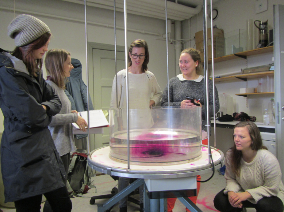
One experiments that has been run in GEOF130 forever is the “Ekman spiral” experiment. A tank filled with water is spun up to solid body rotation on a rotating table.

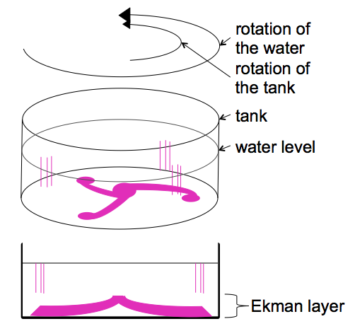
Then the tank is slowed down. The resulting friction between the water body and the tank creates a bottom Ekman spiral.

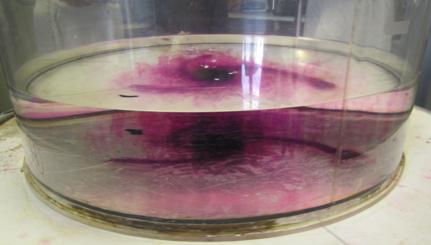
In the lab, you can observe the Ekman depth by looking into the tank from the side:

I’m showing you here what they see, except that you have a big advantage: The camera was mounted on the rotating table, so instead of watching the tank rotate in front of you (which makes it really difficult to focus on features without getting seasick) you are actually rotating with the tank.

It is very difficult to capture on video or photo, but Pierre and I are doing our best.

Stay tuned for a nice Ekman movie coming up soon!

Ship-generated internal waves

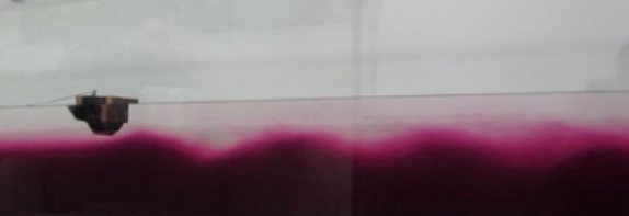
A tank experiment showing ship-generated internal waves.

When entering a fjord from the open ocean by ship, it can sometimes be noted that the speed of the ship changes even though apparently nothing else changed – the wind didn’t change, the position of the sails didn’t change, the settings on the engine didn’t change – whatever was driving the ship didn’t change. And yet, the ship slowed down. How can that be?

According to the legend (that I like to propagate in my classes), when this phenomenon was first noticed, people attributed it to sea monsters latching onto the ship and slowing it down. Or if not monsters, than at least mollusks and other not-quite mostery monsters. But then Bjerknes came along and, together with Ekman, set up experiments that explain what is taking all the energy away from propulsion. I’ll give you a hint:

Yes – the ship excites internal waves at a density interface. Since the stratification in a fjord is much stronger than in the ocean, driving into a fjord means loosing a lot more energy towards the generation of internal waves.

See the movie here:

Water seeks its level.

A solution for the siphon problem of the fjord circulation experiment.

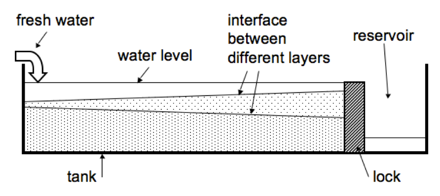
After having run the fjord circulation experiments for several years in a row with several groups of students each year, Pierre and I finally figured out a good way to keep the water level in the tank constant. As you might remember from the sketch in the previous post or can see in the figure below, initially we used to have the tank separated in a main compartment and a reservoir.

 But there were a couple of problems associated with this setup. Once, the lock separating the two parts of the tank fell over during the experiment. Then there are bound to be leaks. Sometimes we forget to empty the reservoir and the water level rises to critical levels. In short, it’s a hassle.

So the next year, we decided to run the experiment in a big sink and tip the tank slightly, so that water would just flow out at the lower end at the same rate that it was being added on the other side. Which kinda worked, but it was messy.

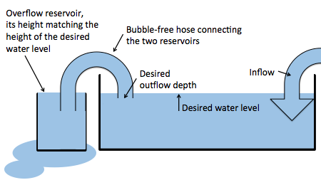
So this year, we came up with the perfect solution. The experiment is still being run in a sink, but now a hose, completely filled with water, connects the main tank with a beaker. The hight of the rim of the beaker is set to the desired water level of the big tank. Now when we add water to the big tank, there is an (almost – if the hose isn’t wide enough) instant outflow, so the water level in the tank stays the same.

Tankausfluss

New setup: A bubble-free hose connecting the tank and a reservoir to regulate the water level in the tank.

This way, we also get to regulate the depth from where the outflowing water is being removed. Neat, isn’t it?

Filling the tank

A movie of patterns observed in the flow when filling the tank for this experiment.

Even though there are tons of scientific things to discuss with this movie, like the different refraction of light in the two layers of different densities, or the filaments, or the restratification processes, I am mainly posting this because I think it is beautiful. Enjoy!

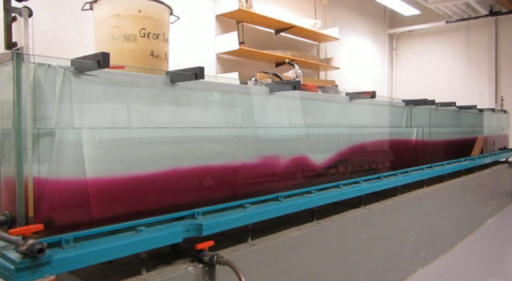
Details of lee waves in the tank.

A movie focusing on details of the lee waves in the tank.

In this post, we investigated lee waves in a tank in a general way. Here, I want to show a detail of those lee waves:

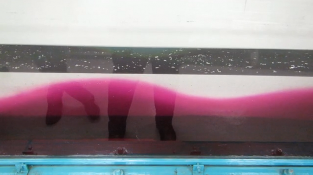
In this movie, the concept of hydraulic control becomes visible. On the upstream side of the mountain, the dense water layer forms a reservoir which is slightly higher than the mountain. On top of the mountain and towards its lee side, the layer of denser water is stretched thin and has a smooth surface until about half way down the mountain, where waves start to form. In this thin, smooth layer, flow speeds are higher than the wave speeds, hence disturbances of the interface are flushed downstream and cannot deform the interface. Only about halfway down the mountain, the phase speed becomes equal to the flow speed, hence waves can both form and stay locked in place relative to the mountain.

For more information on internal waves, check out these posts [which are scheduled to go online over the next couple of days]:

Surface imprints of internal waves

How internal waves in the ocean can be spotted on the surface.

Under certain conditions, internal waves in the ocean can be spotted at the ocean’s surface due to changes in surface roughness or to the movement of floating foam or debris. They can be spotted if half their wavelength is longer than the distance between the interface on which the internal wave is traveling and the water surface, so that the orbital movement caused by the internal waves reaches the water surface. In the tank, they can also be seen – for example by adding small floating particles to the water surface.

MVI_3064

Internal wave in a tank. Seen from the side due to different coloring of the two layers, and on the surface in the distribution of floating tracer.

In the movie below, you can see the interface between water layers of different densities and the water surface with particles on it. The particles make it easy to spot how the water surface is being stretched and squeezed as internal waves travel through underneath.

For more information on internal waves, check out these posts [which are scheduled to go online over the next couple of days]:

Internal (lee) waves in a tank.

Lee wave experiment in a large tank with a moving mountain.

In this previous post, we talked about internal waves in a very simple experiment. But Geophysical Institute has a great tank to do lee wave experiments with that I want to present here (although it doesn’t seem to be clear what will happen to the tank when the remodeling of the main building starts in November – I hope we’ll be able to save the tank!). I think it has originally been used for real research, but these days the GEOF130 lab is the only time this tank gets used.

MVI_2787_01

Tank for internal lee wave experiments – a “mountain” is moved through the tank and generates internal waves.

In this tank, a “mountain” can be moved all the length of the tank through more or less stagnant water, thereby simulating a current going over a non-moving mountain (which might be a slightly more realistic setup). At the lee of the mountain, lee waves form on the interface between two water layers of different density.

For more information on internal waves, check out these posts [which are scheduled to go online over the next couple of days]: