Tag Archives: solid body rotation

Rotating vs non-rotating turbulence

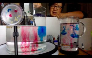
Last Thursday, Torge & I invited his “atmosphere & ocean dynamics class” to a virtual excursion into my kitchen — to do some cool experiments. As you know, I have the DIYnamics rotating table setup at home, so this is what it looked like:

We did two experiments, the very boring (but very important) solid body rotation, and then the much more exciting (and quite pretty, see pic at the very top or movie below!) comparison of turbulence in a non-rotating and a rotating system.

We didn’t manage to record the class as we had planned, so I redid & recorded the experiments. Here are 8 minutes of me talking you through it. Enjoy!

Solid body rotation

Several of my friends were planning on teaching with DIYnamics rotating tables right now. Unfortunately, that’s currently impossible. Fortunately, though, I have one at home and enjoy playing with it enough that I’m

  1. Playing with it
  2. Making videos of me playing with it
  3. Putting the videos on the internet
  4. Going to do video calls with my friends’ classes, so that the students can at least “remote control” the hands-on experiments they were supposed to be doing themselves.

Here is me introducing the setup:

Today, I want to share a video I filmed the spinup of a tank until it reaches solid body rotation. To be clear: This is not a polished, stand-alone teaching video. It’s me rambling while playing. It’s supposed to give students an initial idea of an experiment we’ll be doing together during a video call, and that they’ll be discussing in much more depth in class. Watching a tank until it reaches olid body rotation is probably the most boding tank experiment ever done, but understanding the concept of solid body rotation and why we need it in tank experiments is the foundation of everything we do on a rotating tank. So here we go!

Taylor column

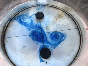
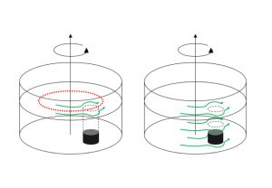
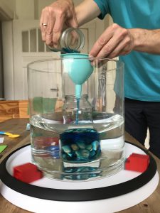
I was super keen on trying the Taylor column experiment, but maybe I expected things to look too much like my sketch below, or my technique isn’t quite perfect yet, but in any case, the results don’t look as good as I had hoped.

This is the setup I was aiming for:

  • put ice hockey puck (two in our case), ca 1/5th water depth, ca 1/4 diameter of tank
  • rotating our tank at 5rpm (ca 7 on GFI’s large tank’s display) with the obstacle in the water until solid body rotation is reached (We know that solid body rotation is reached if paper bits distributed on surface all rotate at same rate as the tank).
  • change the rotation rate a tiny little bit so water moves relative to tank and obstacle, i.e. we have created a current flowing in the rotating system.

And here is what happened.

First attempt.

  • tank was rotating way too fast
  • tank wasn’t in solid body rotation because it wasn’t level
  • one of the hockey pucks didn’t stay in place but moved to the edge of the tank as the tank (slowly!) accelerated
  • more confetti on the surface!

But! We see that there is clearly something happening around the hockey puck that seems to deform the curtain of blue dye.


Second attempt.

  • Stopped too rapidly / bumpy

Even though the blue dye curtain moves over the pucks initially, we see that they develop a wake or something, deforming the dye.


Third attempt.

Accidentally deleted the movie, so we will have to make do with a couple of pics I took while the experiment was running.

Slowing down worked a lot better this time round. We clearly see that the dye curtains are deformed around the Taylor columns and don’t move over the pucks.


Fourth attempt.

I think I am finally accepting that this way of introducing dye as a tracer isn’t working as I had hoped…

And this is when my camera decided to stop working…

Fifth attempt.

Back to the basics: Confetti floating on the surface.

Before slowing down, the field of confetti looked like this.

Then, the tank was slowed down and the field got deformed. Some confetti went over the puck, but there is an eddy downstream of it that catches confetti.

And the confetti that went over the puck seem to be stuck there.


Final attempt (for now).

More confetti. This is the situation before slowing down the tank:

Confetti distribution is influenced by the puck similarly to what we saw in the dye: Some confetti are slowed down upstream, some move around the puck.

Eventually, most confetti end up in the puck’s wake.

Taylor column in a rotating tank

For both of my tank experiment projects, in Bergen and in Kiel, we want to develop a Taylor column demonstration. So here are my notes on the setup we are considering, but before actually having tried it.

Since water under rotation becomes rigid, funny things can happen. For example if a current in a rotating system hits an obstacle, even if the obstacle isn’t high at all relative to the water depth, the current has to move around the obstacle as if it reached all the way from the bottom to the surface. This can be shown in a rotating tank, so of course that’s what we are planning to do!

We are following the Weather in a Tank instructions:

  • rotating our tank at 5rpm with the obstacle in the water until solid body rotation is reached (We know that solid body rotation is reached if paper bits distributed on surface all rotate at same rate as the tank).
  • change the rotation rate a little (they suggest as little as -0.1 rpm) so water moves relative to tank and obstacle, i.e. we have created a current flowing in the rotating system.

As the current meets the obstacle, columns of water have to move around the obstacle as if it went all the way from the bottom to the surface. This is made visible by the paper bits floating on the surface that are also moving around the area where the obstacle is located, even though the obstacle is far down at the bottom of the tank and there is still plenty of water over it.

In the sketch below, the red dotted line indicates a concentric trajectory in the tank that would go right across the obstacle, the green arrows indicate how the flow is diverted around the Taylor column that forms over the obstacle throughout the whole water depth.

Or at least that’s what I hope will happen! I am always a little sceptical with tank experiments that require changing the rotation rate, since that’s what we do to show both turbulence and Ekman layers, neither of which we want to prominently happen in this case here. On the other hand, we are supposed to be changing the rotation rate only very slightly, and in the videos I have seen it did work out. But this is an experiment that is supposedly difficult to run, so we will see…

I also came across about a super cool extra that Robbie Nedbor-Gross and Louis Dumas implemented in this demo: a moving Taylor column! when the obstacle is moved, the Taylor column above it moves with it. Check out their video, it is really impressive! However I think implementing this feature isn’t currently very high on my list of priorities. But it would be fun!

Parabolic surface shape of a tank of water in solid body rotation

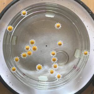
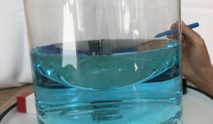
One of the first exercises Torge and I plan on doing with the students in our “dry theory to juicy reality” project is to bring a water-filled tank to solid body rotation and measure rotation, surface height at the center of the tank and the sides, as well as water depth before rotation, and then have them put those together according to theory.

Setup of the experiment as we did it using a glass vase my mom gave me as tank (diameter 24.5 cm). The non-rotating water depth was 9.2 cm. Once we rotated the tank with 10 rotations per 8.6 seconds, the maximum water level at the outside edge of the tank was approximately 10.8 cm, and the minimum 7.9 cm.

Seeing how difficult it is to “measure” the surface heights while the tank is rotating (we chose to draw circles on the outside of the tank at the heights where we thought the water levels were, in order to measure them later on a non-rotating tank), we were quite pleased with those results once we plugged them into the equations.

Calculating the resting water level as arithmetic mean between the rotating maximum value at the rim and the minimum value in the center, we are only off by 0.1 cm, so not too shabby!

And calculating the height difference between resting water level and rotating maximum level from the tangential velocity and radius of the tank, we are only off by 0.4 cm. So all in all, that’s working well!

Btw, below you see the resting water level and above the mark for the rotating maximum value. Quite impressive difference, isn’t it?

Anyway, looking at rotational surfaces and volumes and stuff this way is a lot more fun than doing it the dry theoretical way only! At least that’s what I think ;-)

Spinning dye curtain — when a tank full of water has not reached solid body rotation yet

With all the rotating tank experiments I’ve been showing lately, one thing that comes up over and over again is the issue of solid body rotation.

On our DIYnamics-inspired turntable for our “dry theory to juicy reality” project, Torge and I came up with a fun way to illustrate the importance of full body rotation in tank experiments, again inspired by the DIYnamics team, this time their youtube channel.

For the spinning dye curtain experiment, we start up the rotating table, and then pretty much immediately add in some dye. Below, you see what happens when you add in the dye too late (we waited for 2 minutes here before we added it): The water is so much in solid body rotation already, that we only form columns and 2D flow.

But if we add in the dye right away after starting up the tank, we form these spirals where the water further away from the center is spinning faster than the water right at the center, thus distorting the dye patches into long, thin filaments (Btw, I’ve shown something similar in my “eddies in a jar” experiment earlier, where instead of starting up a turntable I just stirred water in a cylindrical tank).

But as the tank continues to spin up, the eddies eventually stop spinning and the tank turns into solid body rotation. If new dye is added now, only columns form, but they stay intact as if they were, indeed, solid bodies.

But seeing the behaviour of a fluid change within half a minute or so is really impressive and something we definitely want to do in class, too!

Demonstrating Ekman layers in a rotating tank: High pressure and low pressure systems!

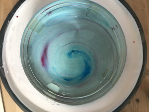
Ekman spirals — current profiles that rotate their direction over depth, caused by friction and Coriolis force — are really neat to observe in a rotating tank. I just found out that they are apparently (according to Wikipedia) called “corkscrew currents” in German, and that’s what they look like, too. I tend to think of Ekman spirals more as an interesting by-product that we observe when stopping the tank after a successful experiment, but they totally deserve to be featured in their own experiments*.

Ekman layers form whenever fluid is moving relative to a boundary in a rotating system. In a rotating tank, that is easiest achieved by moving the boundary relative to the water, i.e. by increasing or decreasing the rotation rate of a tank and observing what happens before the water has adjusted to the new rotation and has reached solid body rotation. Spinning the tank up or down creates high and low pressure systems, respectively, similar to atmospheric weather system.

Creating a low-pressure system: Slowing down the tank

In atmospheric low pressure systems, air moves towards the center of the low pressure system, where it rises, creating the low pressure right there. This situation can probably easiest be modelled by stirring a cup of tea that has some tea leaves still in it. As the surface deforms and water bunches up at the sides, an overturning circulation is set into motion. Water sinks along the side walls and flows towards the center of the cup near the bottom. From there it rises, but any tea leaves or other stuff floating around get stuck in the middle on the bottom because they are too heavy to rise with the current. So there you have your low pressure system!

You can observe the same thing with a rotating tank, except now we don’t stir. The tank is filled with water and spun up to solid body rotation on the rotating table. When the water is in solid body rotation, a few dye crystals are dropped in, leaving vertical streaks as they are sinking to the ground (left plot in the image below).

Then the tank is slowed down. The resulting friction between the water body and the tank creates a bottom Ekman spiral. The streaks of dye that were left when the dye crystals were dropped into the tank move with the water when the tank is slowed down. In the upper part of the tank, the dye stripes stay vertical. But at the bottom, within the Ekman layer, they get deformed as the bottom layer lifts up, and thus show us the depth over which the water column is influenced by bottom friction (see black double arrow in the right plot in the picture below). Again, we have created a low pressure system with a similar overturning circulation as we saw in the tea cup.

In the bottom right corner of the image above, we see a top view of the tank with the trajectory the dye is taking from the spot where it rested on the ground before the rotation of the tank changed.

Looking into the tank with a co-rotating camera, we can also observe the Ekman depth, i.e. the depth that is influenced by the bottom: We see a clear distinction between the region where the dye streaks from the falling crystals are still vertical and the bottom Ekman layer, where they are distorted, showing evidence of the friction with the bottom.

So this was what happens when water is spinning relativ to a slower tank (or a non-rotating cup) — the paraboloid surface is adjusting to one that is more even or completely flat. But then there is also the opposite case.

Creating a high-pressure system: Spinning up the tank

If we take water that is at rest and start spinning the tank (or spin a moving tank faster suddenly), we create a high pressure system until we again reach solid body rotation.

Again, we dropped dye crystals when the water was in solid body rotation (or in solid body without rotation) before we start the spinup, as we see in the left plot below.

Now the sudden spinning of the boundaries relative to the body of water creates a high pressure system with the bottom flow outward from the center, which again we see in the deformation of the dye streaks. The Ekman depth is again the depth over which the dye streaks get bent, below the water column that isn’t influenced by friction where they still have their original vertical shape.

In the bottom right corner of the image above, we see a top view of the tank with the trajectory the dye is taking from the spot where it rested on the ground before the rotation of the tank changed.

Here is what this experiment looks like in a movie:

So here we have it. High pressure and low pressure systems in a tank!

*Which I actually did before, both in a rotating tank as well as on a Lazy Susan.

Working on our own affordable rotating table for oceanographic experiments!

Inspired by the article “Affordable Rotating Fluid Demonstrations for Geoscience Education: the DIYnamics Project” by the Hill et al. (2018), Joke, Torge and I have been wanting to build an affordable rotating table for teaching for a while now. On Saturday, we met up again to work on the project.

This post is mainly to document for ourselves where we are at and what else needs to happen to get the experiments working.

New this time: New rotating tables, aka Lazy Susans. After the one I’ve had in my kitchen was slightly too off-center to run smoothly, we bought the ones recommended by the DIYnamics project. And they work a lot better! To center our tank on the rotating table and keep it safely in place, we used these nifty LEGO and LEGO Duplo contraptions, which worked perfectly.

We also used a LEGO contraption to get the wheel close enough to drive the rotating table. The yellow line below shows where the rim of the rotating table’s foot needs to sit.

And this is how the engine has to be placed to drive the rotating table.

First attempt: Yes! Very nice parabolic surface! Very cool to see time and time again!

Now first attempt at a Hadley cell experiment: A jar with blue ice is placed at the center of the tank. Difficulties here: Cooling sets in right away, before the rotating tank has reached solid body rotation. That might potentially mess up everything (we don’t know).

So. Next attempt: Use a jar (weighted down with stones so it doesn’t float up) until the tank has reached solid body rotation, then add blue ice water

Working better, even though the green dye is completely invisible…

We didn’t measure rotation, nor did we calculate what kind of regime we were expecting, so the best result we got was “The Heart” (see below) — possibly eddying regime with wavenumber 3?

Here is what we learned for next time:

  • use better dye tracers and make sure their density isn’t too far off the water in the tank
  • use white  LEGO bricks to hold the tank in place (so they don’t make you dizzy watching the tank)
  • measure the rotation rate and calculate what kind of regime we expect to see — overturning or eddying, and at which wave number (or, even better, the other way round: decide what we want to see and calculate how to set the parameters in order to see it)
  • use white cylinder in the middle so as to not distract from the circulation we want to see; weigh the cylinder down empty and fill it with ice water when the tank has reached solid body rotation
  • give the circulation a little more time to develop between adding the cold water at the center and putting in dyes (at least 10 minutes)
  • it might actually be worth reading the DIYnamics team’s instruction again, and to buy exactly what they recommend. That might save us a lot of time ;-)

But: As always this was fun! :-)

P.S.: Even though this is happening in a kitchen, I don’t think this deserves the hashtag #kitchenoceanography — the equipment we are using here is already too specialized to be available in “most” kitchens. Or what would you say?

Water not in solid body rotation yet

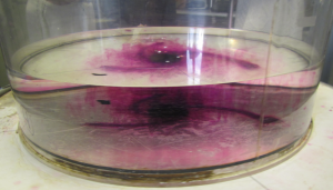
Confusing students even more by discussing how momentum is being transferred from the tank to the water.

As you remember, we are preparing for the Ekman experiment and need to spin up the tank to solid body rotation.

We had started discussing how, when observed from the co-rotating camera, particles seem to be slowing down relative to the coordinate system underneath the tank as we are approaching solid body rotation.

And this is where I usually confuse the students even more, because I start talking about how momentum is being transferred from the tank to the water. For that, I point out how when observing the tank from the non-rotating framework, the particles further away from the center are moving faster than the ones closer towards the center…

(and on the screen: particles closer to the center are moving faster than the ones further away).

Why is that?

Well, for exactly the same reason we can use this setup to simulate Ekman spirals: Because when the tank is sped up or slowed down, this initially creates friction with the water inside. And as the layer that is in direct contact with the tank is brought to the same speed as the tank, it changes its velocity relative to the next layer, which creates friction and influences the movement of this second layer. And so on and so forth.

I think that it is really useful to point this out, and in some of the groups students jump at it and understand where I am going right away, but in other groups I just cannot phrase it in a way that they understand me. Or maybe they are just not as fascinated as I am by being able to see how friction inside water propagates momentum and hence don’t get excited? Who knows.

[Thanks, Pierre, for your help with the filming!]

Water in solid body rotation.

Spinning up a tank until all water particles move with the same angular velocity.

Before running the Ekman spiral experiment, the tank needs to be spun up to solid body rotation. Even though the concept itself is not difficult, it seems to be difficult to determine when a body of water has reached the point where it rotates as a solid body. So here is my attempt to sort my thoughts well enough to explain it better next time I teach this experiment.

Firstly: Solid body rotation of water in a tank basically means that every water molecule is at rest relative to the tank (neglecting thermal movement). This means that over any given period of time, particles that started out on a straight line going radially outwards from the centre will still be on straight line going radially outwards from the centre, with the same radii as initially.

But since we are usually not rotating with the tank, this is pretty hard to observe from a non-rotating frame. Enter the mounted camera rotating with the tank (and, I think, the confusion).

When we start up the rotation of the tank, the water is initially at rest in the frame of the lab. This means that for a counter-clockwise rotating table, particles on the water surface appear to be moving clockwise when observed on the screen.

As time goes by, the water inside the tank starts spinning with the tank, and with it the particles on its surface. On the screen, this appears as though the particles are slowing down.

When the particles don’t move any more relative to the coordinate system underneath the tank, the water is moving with the same speed as the tank and solid body rotation has been reached.

Part 2 will shortly be uploaded, looking into how momentum is being transferred from the tank to the water.