Tag Archives: currents

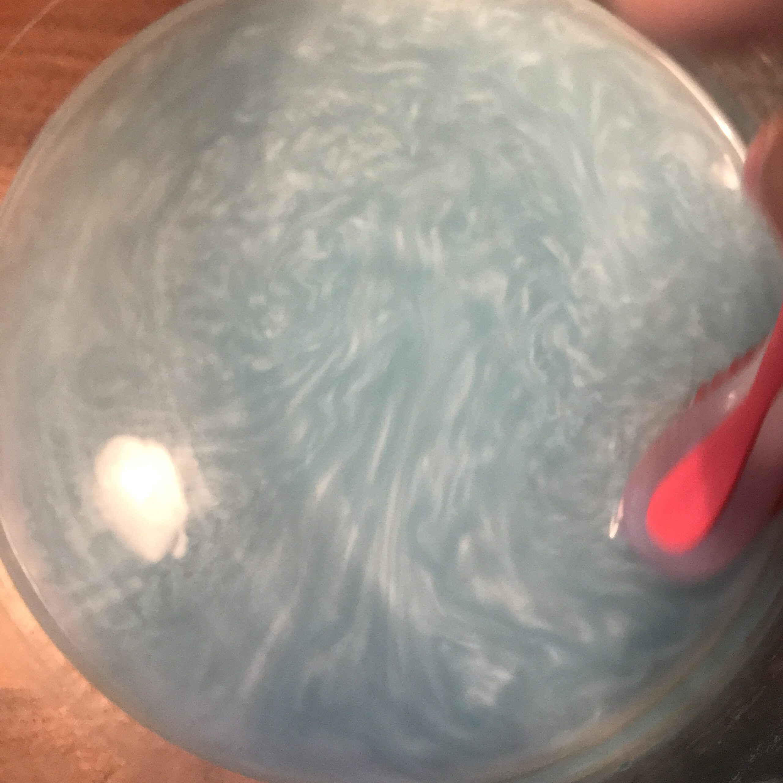
Rheoscopic fluid

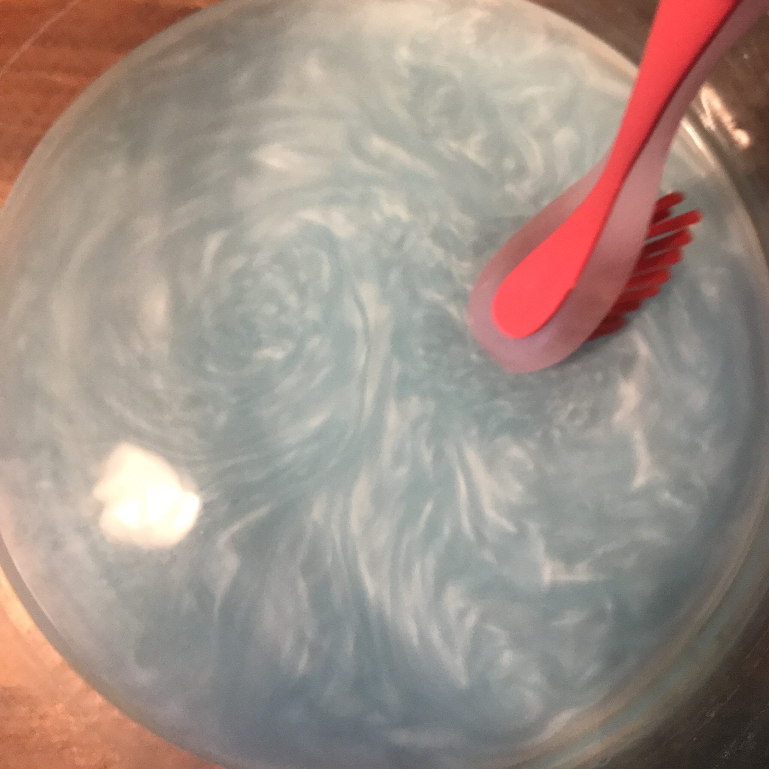
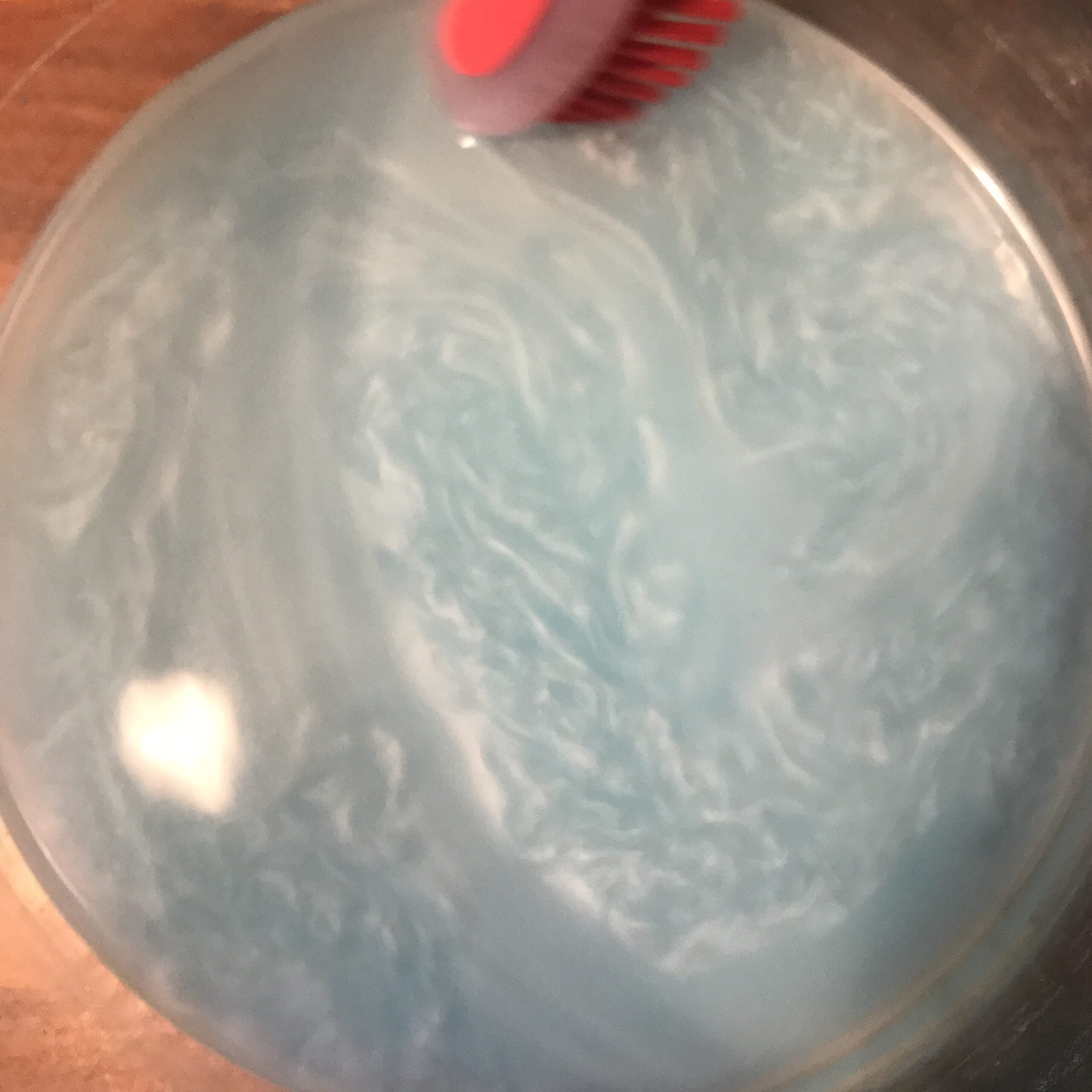
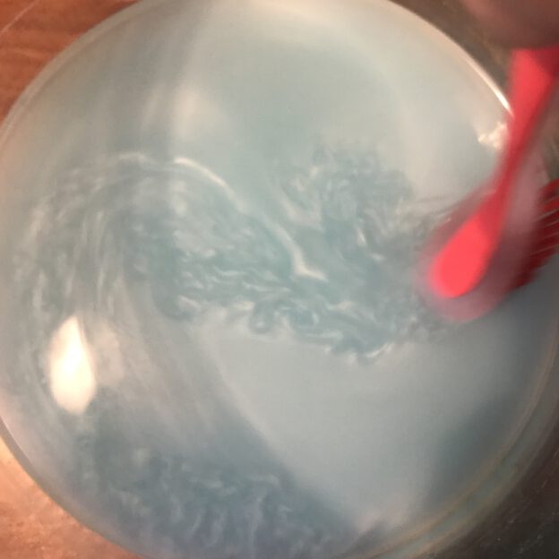
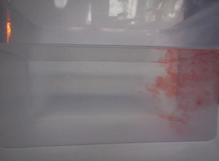
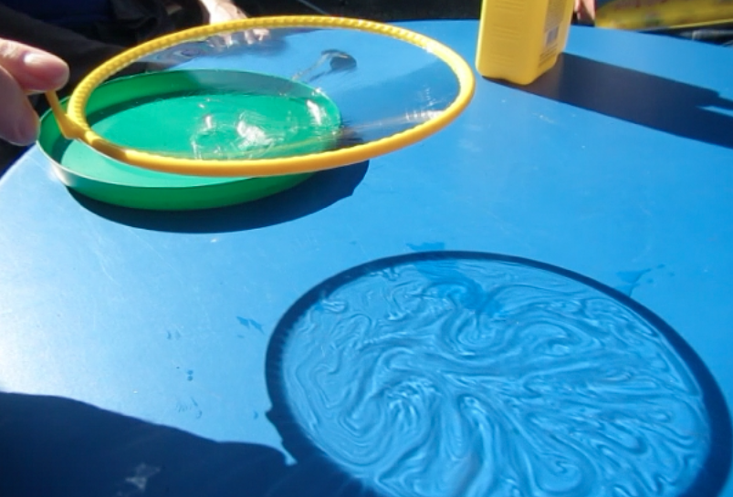
I just wanted to quickly clean my tank… But then it was too pretty, so I guess the rheoscopic (“current showing”) fluid gets to stay a little longer. What an amazing toy :-)

Check out the video at the bottom!!!

Recipe after Borrero-Echeverry, Crowley & Riddick (2018), then added blue food dye.

Totally not the focus of our experiments, but so beautiful! Kelvin-Helmholtz instabilities

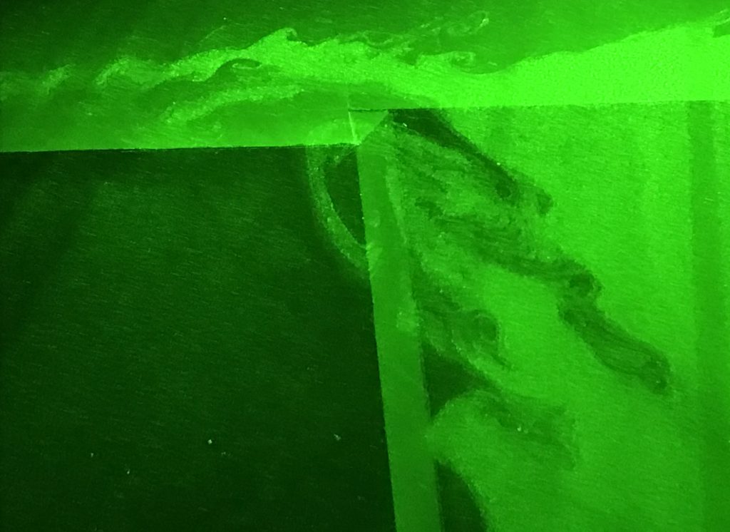
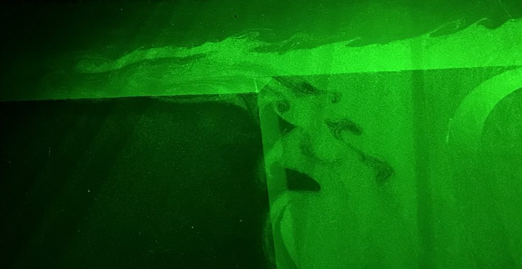
This is really not the focus of our experiments here in Grenoble, but they are too nice not to show: Kelvin-Helmholtz instabilities!

Sheer instabilities in the flow

Sheer instabilities in the flow

They showed up really nicely in our first experiment, when we only had neutrally-buoyant particles in our source water (and not yet in the ambient water). The water that shows up as the lighter green here is thus water that originally came from the source (and at this point has recirculated out of the canyon again).

Sheer instabilities in the flow

Sheer instabilities in the flow

I get so fascinated with this kind of things. How can anyone possibly not be interested in fluid dynamics? :-)

2017-09-12-17-07-53

Watch the movie below to see them in motion! The scanning works as explained here.


How the strength of the current influences which path it takes. First observations!

Depending on how strong a current we introduce in the 13-m-diameter rotating tank to simulate the strength of the coastal current in Elin et al.’s 2016 article (link on our blog, link to the article), it takes different pathway along and across our topography.

According to theory, we expected to see something like what I sketched below: The stronger the current, the more water should continue on straight ahead, ignoring the canyon that opens up perpendicular to the current’s path at some point. The weaker the current, the more should take a left into the canyon.
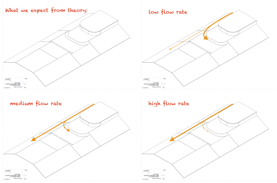
What we expect from theory

What we expect from theory

We have now done a couple of experiments, and here you get a sneak preview of our observations!

Small disclaimer beforehand: What you see below are pictures taken with my mobile phone, and the sketched pathways are what I have observed by eye. This is NOT how we actually produce our real data in our experiments: We are using cameras that are mounted in very precisely known positions, that have been calibrated (as described here) and that produce many pictures per second, that are painstakingly analysed with complex mathematics and lots of deep thought to actually understand the flow field. People (hi, Lucie!) are going to do their PhDs on these experiments, and I am really interpreting on the fly while we are running experiments. Also we see snapshots of particle distribution, and we are injecting new particles in the same tank for every experiment and haven’t mixed them up in between, so parts of what you see might also be remnants of previous experiments. So please don’t over-interpret! :-)

So here we go: For a flow rate of 10 liter per minute (which is the lowest flow rate we are planning on doing) we find that a lot of the water is going straight ahead, while another part of the current is following the shelf break into the canyon.
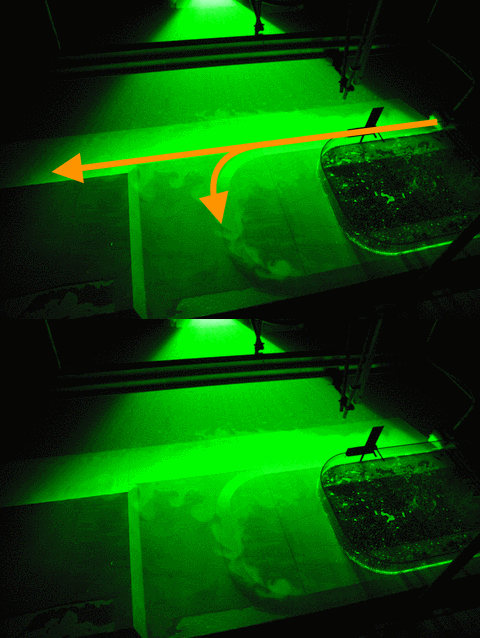
First observations - low flow rate (10l/min)

First observations – low flow rate (10l/min)

For 20 liter per minute, our second lowest flow rate, we find that parts of the current is going straight ahead, parts of it is turning into the canyon, and a small part is following along the coastline (Which we didn’t expect to happen). However it is very difficult to observe what happens when the flow is in a steady state, especially when velocities are low, since what jumps at you is the particle distribution that is not directly related to the strength of the current which we are ultimately interested in… So this might well be an effect of just having switched on the source and the system still trying to find its steady state.
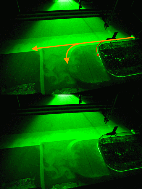
First observations - higher flow rate (20l/min)

First observations – higher flow rate (20l/min)

The more experiments we run in a day after only stirring the particles up in the morning, the more difficult it gets to observe “by eye” what is actually happening with the flow. But that’s what will be analysed in the months and years to come, so maybe it’s good that I can’t give away too many exciting results here just yet? ;-)
Temperature-driven overturning experiment – the easy way

In my last post, I showed you the legendary overturning experiment. And guess what occurred to me? That there is an even easier way to show the same thing. No gel pads! (BUT! And that is a BIG BUT! Melting of ice cubes in lukewarm water is NOT the process that drives the “real” overturning! For a slightly longer version of this post check this out).

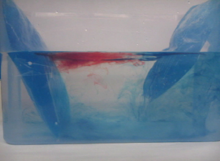
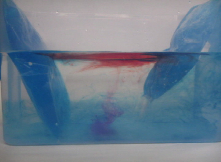
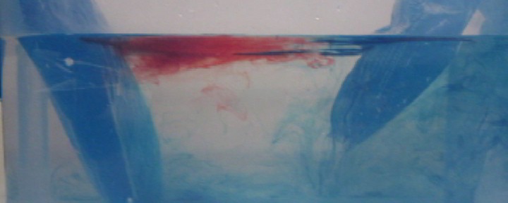
So. Tank full of luke warm water. Red dye on one end. Spoiler alert: This is going to be the “warm” end.

overturning-ice-1Now. Ice cubes on the “cold” end. For convenience, they have been dyed blue so that the cold melt water is easily identifiable as cold.
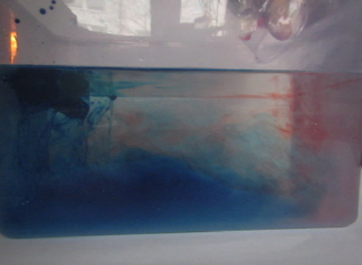
overturning-ice-2A very easy way to get a nice stratification! And as you see in the video below, awesome internal waves on the interface, too.
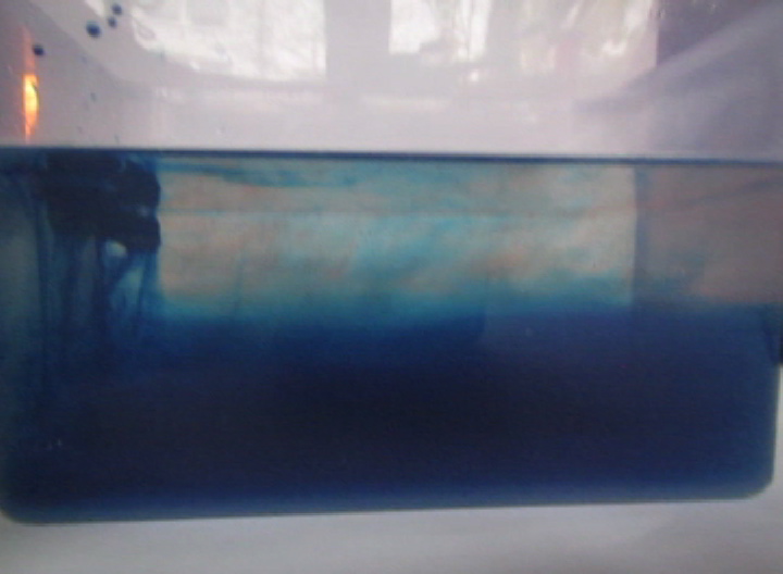
overturning-ice-3

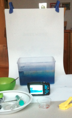
And because I know you like a “behind the scenes”:

I took this picture sitting on my sofa. The experiment is set up on the tea table. The white background is a “Janosch” calendar from 15 years ago, clipped to the back of a chair. And that is how it is done! :-)

Screen shot 2015-11-02 at 3.41.24 PM

Overturning experiment. By Mirjam S. Glessmer

A very simple overturning experiment for outreach and teaching

For one of my side-projects I needed higher-resolution photos of the overturning experiment, so I had to redo it. Figured I’d share them with you, too.

You know the experiment: gel pads for sports injuries, one hot (here on the left), one cold (here on the right). Blue dye on the cold pad to mark the cold water, red dye on the warm pad as a tracer for warm water.

overturning

Thermally-driven overturning circulation: Warm water flowing near the surface from the warm pad on the left towards the right, cold flow from the cool pad at the bottom right to left.

A circulation develops. If you drop dye crystals in the tank, the ribbon that formed gets deformed by the currents for yet another visualization of the flow field.

overturning2

Thermally-driven overturning circulation. In the middle of the tank you see a ribbon of dye, caused by falling dye crystals, being transformed by the currents in the tank.

Lighting is a problem this time of year. I chose natural light over artificial, and it came out ok, I think.

And here is the video:

Currents caused by thrusters

Or: fast inflow into nearly stagnant water body

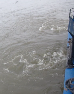
Did you ever notice how when certain ferries dock, they stop, already parallel to the dock, a couple of meters away from the dock and then just move sideways towards the dock? Usually they don’t even move passenger ferries any more, just use thrusters to keep them steady while people get on and off.

MVI_0977

Currents caused by thrusters of a harbor ferry in the port of Hamburg

But why this weird sideward motion?

One reason is the Coanda effect – the effect that jets are attracted to nearby surfaces and follow those surfaces even when they curve away. You might know it from putting something close to a stream of water and watching how the stream gets pulled towards that object, or from a fast air stream that can lift ping pong balls. So if the ship was moving while using the thrusters, the jets from the thrusters might just attach themselves to the hull of the ship and hence not act perpendicularly to the ship as intended.

But I think there is a secret second reason: Because it just looks awesome :-)

Marsigli’s experiment

Density-driven flow.

The experiment presented in this post was first proposed by Marsigli in 1681. It illustrates how, despite the absence of a difference in the surface height of two fluids, currents can be driven by the density difference between the fluids. A really nice article by Soffientino and Pilson (2005) on the importance of the Bosporus Strait in oceanography describes the conception of the experiment and includes original drawings.

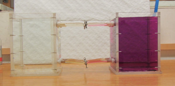
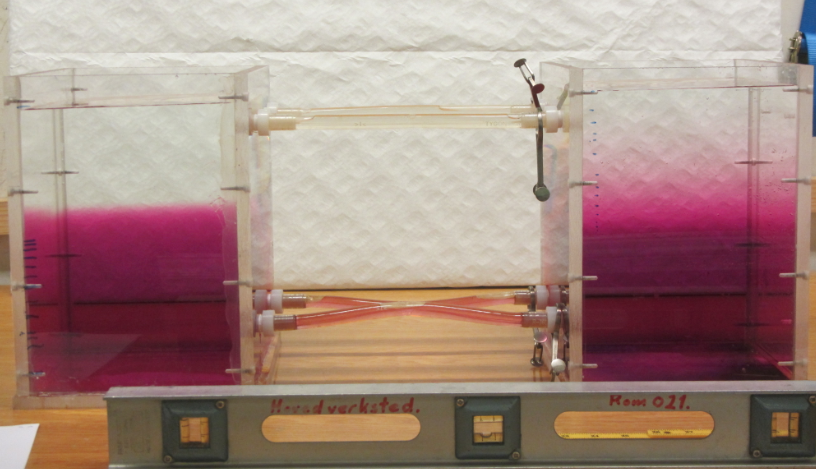
The way we conduct the experiment, we connect two similar tanks with pipes at the top and bottom, but initially close off the pipes to prevent exchange between tanks. One tank is filled with fresh water, the other one with salt water which is dyed pink. At a time zero we open the pipes and watch what happens.
Marsigli1

Two tanks, one with clear freshwater and one with pink salt water, before the connection between them has been opened.

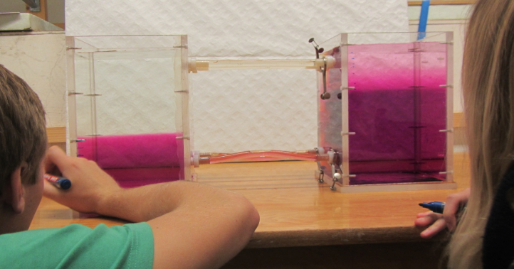
As was to be expected, a circulation develops in which the dense salt water flows through the lower pipe into the fresh water tank, compensated by freshwater flowing the opposite way in the upper pipe.
Marsigli3

The two tanks equilibrating.

We measure the height of the interface between the pink and the clear water in both tanks over time, and watch as it eventually stops changing and equilibrates.
Marsigli4

The two tanks in equilibrium.

Usually this experiment is all about density driven flows, as are the exercises and questions we ask connected to it. But humor me in preparation of a future post: Comparing the height of the two pink volumes and the two clear volumes we find that they do not add up to the original volumes of the pink and clear tanks – the pink volume has increased and the clear volume decreased.
How did that happen?